Last Updated: April 2026 | Written for beginners and engineers new to Rockwell Automation systems.
Allen Bradley PLC programming is one of the most in-demand skills in North American industrial automation. Whether you are an engineer starting out, a technician looking to advance, or a student entering the field — mastering this platform opens doors to thousands of well-paying jobs across manufacturing, automotive, food and beverage, oil and gas, and pharmaceutical industries.
Rockwell Automation — the company behind the Allen Bradley brand — holds the largest PLC market share in North America. On any given day there are thousands of open positions requiring Studio 5000 and CompactLogix experience. If you plan to work in North American manufacturing, understanding Allen Bradley PLC programming is essential.
This complete guide covers everything from software installation to writing your first ladder logic program:
- The Allen Bradley PLC families — MicroLogix, Micro800, CompactLogix, ControlLogix
- Which software to use — Studio 5000, RSLogix 500, Connected Components Workbench
- How to get free software and simulation without buying any hardware
- How tag-based addressing works in Studio 5000
- Step-by-step guide to creating your first project
- The most important ladder logic instructions — XIC, XIO, OTE, TON, CTU and more
- How the Allen Bradley platform compares to Siemens
- Common mistakes beginners make and how to avoid them
What Is Allen Bradley PLC Programming?
Allen Bradley PLC programming is the process of writing control logic for Rockwell Automation programmable logic controllers to automate machines and industrial processes. The Allen Bradley brand is manufactured by Rockwell Automation, headquartered in Milwaukee, Wisconsin, USA.
Unlike traditional relay-based control panels that required physical rewiring to change machine behaviour, a PLC runs a software program that can be modified, updated and downloaded without touching a single wire. This makes PLC-based automation far more flexible, faster to commission, and easier to troubleshoot than any relay panel.
The platform uses Studio 5000 Logix Designer as its primary programming environment for modern CompactLogix and ControlLogix PLCs. The most widely used language is Ladder Logic — a graphical programming language based on electrical relay diagrams, deliberately designed to be understood by engineers and technicians without a software development background.
| Feature | Detail |
|---|---|
| Brand | Allen Bradley — manufactured by Rockwell Automation |
| Primary software | Studio 5000 Logix Designer (formerly RSLogix 5000) |
| Main language | Ladder Logic — most widely used in industry |
| Network protocol | EtherNet/IP — open standard managed by ODVA |
| Addressing | Tag-based — descriptive text names for all variables |
| Market | Dominant in North America — also used globally |
| Free software | Connected Components Workbench for Micro800 — free forever |
Allen Bradley PLC Programming – Which PLC Family Do You Need?
Before diving into software and code it is important to understand which PLC family you are working with. Each family uses different software and is designed for a different scale of application. Understanding the differences helps you choose the right hardware from day one.
| PLC Family | Type | Software | IO Capacity | Best Application |
|---|---|---|---|---|
| Micro800 series | Compact — fixed IO | Connected Components Workbench (free) | Up to 48 IO | Learning, simple OEM machines, low budget |
| MicroLogix 1100/1400 | Compact — fixed IO | RSLogix 500 (free version) | Up to 80 IO | Simple standalone machines, legacy systems |
| CompactLogix 5380 | Compact — modular | Studio 5000 Logix Designer | Up to 31 modules | Packaging, material handling, food — most common in industry |
| ControlLogix 5580 | Full modular rack | Studio 5000 Logix Designer | Unlimited racks | Large plants, automotive lines, advanced process control |
| GuardLogix 5580 | Safety modular rack | Studio 5000 Logix Designer | Unlimited racks | Safety-critical applications — SIL 2 / PLd rated systems |
CompactLogix vs ControlLogix – Which Is Better for Allen Bradley PLC Programming?
Both CompactLogix and ControlLogix use identical Studio 5000 software and identical ladder logic instructions. The difference is scale and hardware architecture:
- CompactLogix — compact modular design, up to 31 local IO modules, ideal for machines and medium-sized applications. This is the most commonly encountered PLC in North American manufacturing and the best starting point for most engineers.
- ControlLogix — full rack-based modular design, unlimited expansion through multiple racks, supports CPU redundancy, advanced motion control and safety integration. Used for large production lines, complex process plants, and high-availability systems.
💡 Recommendation for Beginners: Start with CompactLogix and Studio 5000. Once you understand the software environment, tag addressing, and ladder logic instructions — the transition to ControlLogix takes only a few days because the programming is identical. Read our related guide: Compact vs Modular PLC Guide
Allen Bradley PLC Software – Complete Programming and Design Stack
The Allen Bradley PLC software ecosystem from Rockwell Automation includes more than just a programming environment. A complete Allen Bradley PLC software stack covers programming, HMI development, communication drivers, simulation, system design, and data historian — all working together as an integrated automation platform. This section covers all the essential AB PLC software tools every engineer working with Rockwell Automation systems must know.
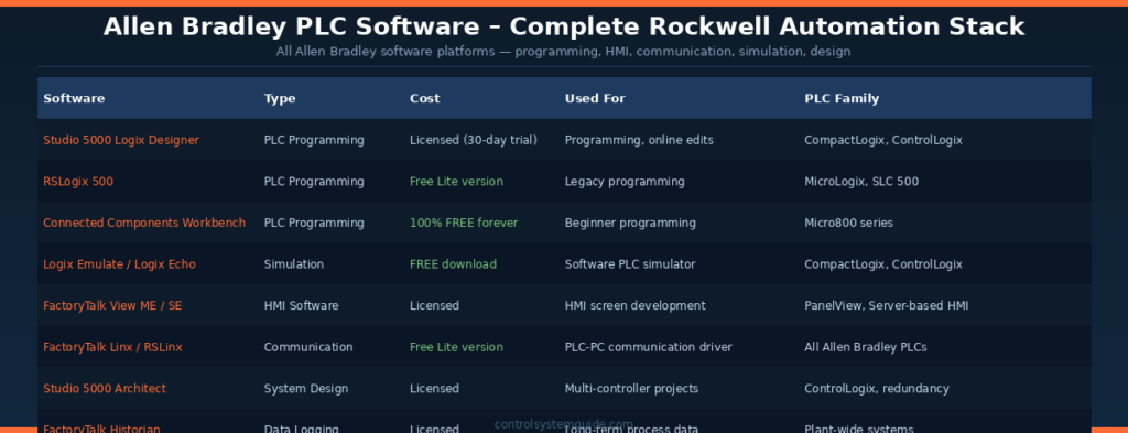
Allen Bradley PLC Programming Software – The Core Tools
The choice of Allen Bradley PLC programming software depends entirely on which PLC family you are working with. Allen Bradley offers four different programming environments — each optimized for a specific PLC line. Understanding which AB PLC software to use saves hours of confusion when starting a new project.
| Allen Bradley PLC Software | Cost | For PLC Family | Best For |
|---|---|---|---|
| Studio 5000 Logix Designer | Licensed (30-day free trial) | CompactLogix 5380, ControlLogix 5580, GuardLogix | Professional programming — most widely used AB PLC software in industry today |
| RSLogix 500 | Free Lite version available | MicroLogix 1000/1100/1400, SLC 500 | Learning legacy systems and small standalone applications |
| Connected Components Workbench | 100% Free forever | Micro820, Micro830, Micro850, Micro870 | Beginner Allen Bradley PLC software — no time limits |
| RSLogix 5 | Licensed (limited use) | PLC-5 (legacy) | Maintaining legacy PLC-5 installations |
Studio 5000 Logix Designer – The Flagship Allen Bradley PLC Software
Studio 5000 Logix Designer is the flagship Allen Bradley PLC programming software for modern CompactLogix and ControlLogix controllers. Previously known as RSLogix 5000 (versions 1-20), it was rebranded as Studio 5000 starting from version 21. Most professional Allen Bradley PLC software programming today happens in Studio 5000 because it supports all 5 IEC 61131-3 programming languages and includes advanced features like motion control, safety integration, and tag-based addressing.
| Feature | Detail |
|---|---|
| Programming languages | Ladder Logic, Function Block Diagram, Structured Text, Sequential Function Chart, Instruction List |
| Addressing | Tag-based — descriptive names instead of memory addresses |
| Online editing | Full online edits in RUN mode without stopping the PLC |
| Motion control | Integrated motion programming for Kinetix servo drives |
| Safety | GuardLogix safety controllers programmed in same environment |
| System requirements | Windows 10/11 64-bit, 16GB RAM recommended, 30GB disk space |
Connected Components Workbench – Free Allen Bradley PLC Software
Connected Components Workbench (CCW) is the completely free Allen Bradley PLC software designed for the Micro800 series controllers. CCW has no time limits, no tag count restrictions, and includes a built-in software simulator. This makes it the perfect entry point for anyone learning Allen Bradley PLC programming without spending money on Studio 5000 licenses.
| Feature | Detail |
|---|---|
| Cost | 100% free — no time limits, no feature restrictions |
| Languages | Ladder Diagram, Function Block Diagram, Structured Text |
| Built-in simulator | Yes — Micro850 simulator included |
| Supported PLCs | Micro820, Micro830, Micro850, Micro870, Micro870 2080-LC70 |
| Built on | Microsoft Visual Studio Shell — modern, clean interface |
| Download | Direct from Rockwell Automation website (free registration required) |
💡 Free Allen Bradley PLC Software Learning Path: Download Connected Components Workbench (free forever, no expiration) → practice ladder logic on the Micro850 simulator → then download Studio 5000 Logix Designer 30-day trial with Logix Emulate for CompactLogix practice. This complete free Allen Bradley PLC software learning path costs nothing and covers beginner through intermediate skills.
Logix Emulate – Allen Bradley PLC Software Simulator
Logix Emulate (now called Logix Echo in newer versions) is the free Allen Bradley PLC software simulator that runs a complete CompactLogix or ControlLogix controller in software on your PC. Once installed, Logix Emulate lets you download Studio 5000 programs to a virtual PLC, monitor execution online, and force IO values for testing — exactly like working with real hardware.
Logix Emulate is a separate download from Studio 5000 but is available free of charge from Rockwell Automation. The combination of Studio 5000 trial + Logix Emulate gives you a complete Allen Bradley PLC software development and testing environment without any physical hardware purchase.
FactoryTalk View – Allen Bradley HMI Software
FactoryTalk View is the HMI development software in the Allen Bradley PLC software ecosystem. It comes in two main variants — Machine Edition (ME) for embedded PanelView terminals, and Site Edition (SE) for server-based plant-wide HMI systems. FactoryTalk View integrates seamlessly with Studio 5000 — tag references update automatically when PLC tags change.
| Variant | Used For | Deployment |
|---|---|---|
| FactoryTalk View ME | Machine-level HMI on PanelView terminals | Standalone touch screen panels at machines |
| FactoryTalk View SE | Plant-wide supervisory HMI | Server-client architecture with multiple workstations |
| FactoryTalk Optix | Modern web-based HMI (newer platform) | Browser-based HMI for Industry 4.0 applications |
FactoryTalk Linx – Allen Bradley Communication Software
FactoryTalk Linx (formerly RSLinx Classic and RSLinx Enterprise) is the communication driver software in the Allen Bradley PLC software stack. It handles all data exchange between Studio 5000 / FactoryTalk View / RSLogix 500 and the physical PLCs. A free Lite version is included with most Rockwell software — sufficient for development and small projects.
| Version | Cost | Use Case |
|---|---|---|
| RSLinx Classic Lite | Free | Programming and development workstations |
| FactoryTalk Linx Gateway | Licensed | OPC UA gateway for SCADA/MES integration |
| FactoryTalk Linx Enterprise | Licensed | Production HMI runtime communication |
Other Important Allen Bradley PLC Software Tools
| Software | Function | Used By |
|---|---|---|
| Studio 5000 Architect | Multi-controller system design and configuration | System integrators on large projects |
| FactoryTalk Historian | Long-term process data logging and trending | Plant operations and maintenance teams |
| FactoryTalk AssetCentre | Backup, version control, audit trail for AB programs | Maintenance and IT departments |
| Integrated Architecture Builder | System design, BOM generation, cost estimation | Sales engineers and system designers |
| Motion Analyzer | Motion system sizing and validation | Motion control engineers |
| Emulate3D | 3D virtual factory simulation | Pre-commissioning and operator training |
Allen Bradley PLC Software – Free Download Summary
Here is a complete summary of the Allen Bradley PLC software you can download for free directly from Rockwell Automation, perfect for students, beginners, and engineers learning the platform without budget:
| Free Allen Bradley Software | Get From | Account Needed |
|---|---|---|
| Connected Components Workbench | Rockwell Automation download portal | Free Rockwell account |
| RSLogix Micro Starter Lite | Rockwell Knowledge Base | Free Rockwell account |
| Studio 5000 Logix Designer (30-day trial) | Rockwell Automation product page | Free Rockwell account |
| Logix Emulate / Logix Echo | Rockwell Automation download portal | Free Rockwell account |
| RSLinx Classic Lite | Bundled with Rockwell software | None |
| FactoryTalk View Studio (limited trial) | Rockwell Automation evaluation | Free Rockwell account |
Download these tools from the official Rockwell Automation Allen Bradley software page.
Allen Bradley PLC Programming – Tag-Based Addressing Explained
One of the most significant differences between Studio 5000 and older PLC systems is the tag-based addressing model. This is a concept that confuses engineers coming from older rack-based systems and is worth understanding clearly before writing your first program.
Rack-Based vs Tag-Based Addressing
| Feature | Rack-Based (Old) | Tag-Based (Studio 5000) |
|---|---|---|
| Address format | I:1/0, O:1/3, N7:5, F8:3 | Start_Button, Motor_Run, Tank_Level |
| Readability | Difficult — no meaning in the address | Self-documenting — name describes function |
| Troubleshooting | Must cross-reference address list | Tag name tells you exactly what it controls |
| Platform | RSLogix 500, SLC 500, PLC-5 | Studio 5000, CompactLogix, ControlLogix |
Tag Data Types
Every tag in Studio 5000 has a data type that defines what kind of value it stores. Choosing the correct data type is important for both memory efficiency and program correctness.
| Data Type | Size | Range | Typical Use |
|---|---|---|---|
| BOOL | 1 bit | 0 or 1 | Digital inputs, outputs, status flags — Motor_Running, Valve_Open |
| INT | 16-bit integer | -32,768 to 32,767 | Small integer values — speed references, raw analog values |
| DINT | 32-bit integer | ±2,147,483,647 | Production counts, large integer values, timer presets |
| REAL | 32-bit float | ±3.4 × 10³⁸ | Decimal values — temperature in °C, pressure in bar, flow rate |
| TIMER | Structure | .PRE, .ACC, .EN, .TT, .DN bits | All timer instructions — TON, TOF, RTO |
| COUNTER | Structure | .PRE, .ACC, .CU, .CD, .DN, .OV, .UN bits | All counter instructions — CTU, CTD |
| STRING | 82 bytes | Up to 82 characters | Recipe names, barcode data, operator messages |
| UDT | User defined | Any combination of types | Custom structures for motors, valves, drives |
Tag Scope in Allen Bradley PLC Programming
Tags in Studio 5000 can be either Controller-scope or Program-scope:
- Controller tags — global scope — accessible from every routine in every program in the project. Use for IO tags, shared variables, and any data needed across multiple programs.
- Program tags — local scope — only accessible within the specific program where they are created. Use for internal logic variables that do not need to be shared.
Allen Bradley PLC Programming – Your First Studio 5000 Project
Step 1 — Download and Install the Software
- Go to the Rockwell Automation Studio 5000 product page
- Register for a free Rockwell account (required for download)
- Download the Studio 5000 Logix Designer 30-day trial
- Also download Logix Emulate — the free software PLC simulator
- Install both — requires Windows 10/11 64-bit with minimum 8GB RAM
Step 2 — Create a New Project
- Open Studio 5000 → click New Project
- Select controller type: CompactLogix 5380
- Choose CPU model — for example 5069-L306ER
- Enter a descriptive project name — “Motor_Control_Demo”
- Click OK — Studio 5000 opens with the project tree on the left showing Controller, Tasks, IO Configuration
Step 3 — Add IO Modules
- In the project tree → right-click IO Configuration → Add Module
- Add a digital input module — 5069-IB16 (16-point 24VDC input)
- Add a digital output module — 5069-OB16 (16-point 24VDC output)
- Studio 5000 automatically creates IO tags — Local:1:I.Data.0 through Local:1:I.Data.15 for inputs
- Create alias tags with meaningful names — rename Local:1:I.Data.0 to “Start_Button”
Step 4 — Write Your First Ladder Logic Program
The classic first program for any PLC is a motor start/stop circuit. Here is how it looks in Studio 5000 ladder logic:
| Rung | Logic | Purpose |
|---|---|---|
| 0000 | [XIC Stop_NC] [XIC Start_Button] —— (OTE Motor_Output) —— | Motor starts when Start pressed AND Stop not pressed |
| 0001 | [XIC Stop_NC] [XIC Motor_Output] —— (OTE Motor_Output) —— | Seal-in — motor stays running after Start released |
| 0002 | [XIC Motor_Output] —— [TON Run_Timer PRE:30000] —— | Count 30 seconds (30000ms) of motor run time |
| 0003 | [XIC Run_Timer.DN] —— (OTE Timeout_Alarm) —— | Set alarm if motor runs longer than 30 seconds |
Step 5 — Download and Test with Logix Emulate
- Open Logix Emulate → create a new emulated controller matching your project CPU
- In Studio 5000 → Communications → Who Active → browse to emulated controller
- Click Download → confirm going to RUN mode
- Go online — you can now monitor rungs in real time and force IO tags to test your logic
Allen Bradley PLC Programming – Ladder Logic Instructions Reference
Ladder logic is the dominant language in Studio 5000 and the foundation of all Rockwell Automation controller programming. Understanding these instructions thoroughly is the core skill of any controls engineer working with this platform.
Contact Instructions (Input Side of Rung)
| Instruction | Full Name | Logic | Equivalent |
|---|---|---|---|
| XIC | Examine If Closed | TRUE when tag bit = 1 | Normally Open (NO) contact |
| XIO | Examine If Open | TRUE when tag bit = 0 | Normally Closed (NC) contact |
Output Instructions (Right Side of Rung)
| Instruction | Full Name | Action | Notes |
|---|---|---|---|
| OTE | Output Energize | Sets bit = 1 when rung TRUE, resets to 0 when FALSE | Standard output coil — most common |
| OTL | Output Latch | Sets bit = 1 when rung TRUE — holds state when rung goes FALSE | Retentive set — use with OTU to reset |
| OTU | Output Unlatch | Resets bit = 0 when rung TRUE | Clears an OTL latched bit |
Timer Instructions
| Instruction | Full Name | Function | Example Use |
|---|---|---|---|
| TON | Timer On Delay | Counts up in ms while rung TRUE — .DN sets when .ACC ≥ .PRE | Delay before motor starts — 5 second warm-up |
| TOF | Timer Off Delay | Counts after rung goes FALSE — output stays on during timing | Fan run-on after motor stops |
| RTO | Retentive Timer On | Retains .ACC value when rung goes FALSE — use RES to reset | Accumulated runtime tracking |
Timer preset values are in milliseconds. A 5-second timer has PRE = 5000. A 2-minute timer has PRE = 120000. This is an important difference from Siemens TIA Portal which uses time format (T#5s). For complete timer examples: PLC Timer Guide – TON, TOF, RTO Explained
Counter Instructions
| Instruction | Full Name | Function | Example Use |
|---|---|---|---|
| CTU | Count Up | Increments .ACC on each FALSE-to-TRUE rung transition — .DN sets when .ACC ≥ .PRE | Product count on conveyor |
| CTD | Count Down | Decrements .ACC on each FALSE-to-TRUE transition — .DN sets when .ACC ≤ 0 | Batch size countdown |
| RES | Reset | Resets .ACC to zero and clears all status bits | Reset counter at shift change |
Comparison and Math Instructions
| Instruction | Full Name | TRUE When |
|---|---|---|
| EQU | Equal | Source A = Source B |
| NEQ | Not Equal | Source A ≠ Source B |
| GRT | Greater Than | Source A > Source B |
| LES | Less Than | Source A < Source B |
| GEQ | Greater Than or Equal | Source A ≥ Source B |
| LEQ | Less Than or Equal | Source A ≤ Source B |
| MOV | Move | Copies source value to destination tag |
| ADD | Add | Source A + Source B → Destination |
| SUB | Subtract | Source A − Source B → Destination |
| MUL | Multiply | Source A × Source B → Destination |
| DIV | Divide | Source A ÷ Source B → Destination |
Allen Bradley PLC Programming – Tasks and Program Structure
Studio 5000 organises execution into a hierarchy of Tasks, Programs, and Routines. Understanding this structure is essential before writing anything beyond a simple test program.
| Level | Name | Description |
|---|---|---|
| 1 | Controller | The top level — holds all tasks, programs, tags and IO configuration |
| 2 | Task | Controls when programs execute — Continuous, Periodic, or Event |
| 3 | Program | Logical grouping of routines — one or more per task |
| 4 | Routine | Actual code — ladder logic rungs live here |
Allen Bradley PLC Programming Task Types Explained
| Task Type | Execution | Use For |
|---|---|---|
| Continuous Task | Executes as fast as possible — variable scan time | Main machine control logic — motor control, conveyors, interlocks |
| Periodic Task | Executes at a fixed time interval — e.g. every 10ms | PID loops, data logging, analog scaling — time-critical functions |
| Event Task | Triggered by a specific event — digital input change, motion axis | Emergency stop response, high-speed counter — fastest response |
EtherNet/IP – The Allen Bradley Network Protocol
EtherNet/IP is the industrial Ethernet communication protocol used across the entire Allen Bradley ecosystem. It connects PLCs to remote IO modules, HMIs, variable frequency drives, and other devices over standard Ethernet infrastructure — no proprietary cabling required.
| Feature | Detail |
|---|---|
| Physical layer | Standard Cat5e / Cat6 Ethernet cable and RJ45 connectors |
| RPI | Requested Packet Interval — how often IO data is exchanged (default 10ms) |
| IP address | Each CompactLogix has a built-in Ethernet port — configure IP via BOOTP tool |
| Implicit messaging | Cyclic IO — data updates automatically every RPI interval |
| Explicit messaging | MSG instruction — on-demand read/write between PLCs or to drives |
| Standard body | Managed by ODVA — open standard used by hundreds of vendors |
According to ODVA (Open DeviceNet Vendors Association) — the official EtherNet/IP standards body — EtherNet/IP has over 70 million installed nodes worldwide making it one of the most widely deployed industrial network protocols globally.
Allen Bradley vs Siemens – Side by Side Comparison
| Feature | Allen Bradley (Studio 5000) | Siemens (TIA Portal) |
|---|---|---|
| Primary software | Studio 5000 Logix Designer | TIA Portal V19 |
| Industrial network | EtherNet/IP | PROFINET |
| IO addressing | Tag-based — Motor_Run, Start_Button | Address-based — %I0.0, %Q0.0 |
| Timer preset unit | Milliseconds — PRE:5000 = 5 seconds | Time format — PT:T#5s |
| NO contact instruction | XIC | –||- (standard contact) |
| NC contact instruction | XIO | -|/|- (negated contact) |
| Output coil instruction | OTE | -( )- |
| Program structure | Tasks → Programs → Routines | OBs → FBs → FCs → DBs |
| Free simulation | Logix Emulate (separate download) | PLCSIM (included with TIA Portal) |
| Best free software | Connected Components Workbench | TIA Portal 21-day trial |
| Market dominance | North America | Europe, Asia, Global |
For the complete Siemens platform guide: Siemens S7-1200 Tutorial – Complete Beginner Guide
Common Allen Bradley PLC Programming Mistakes to Avoid
Mistake 1 — Using spaces or hyphens in tag names
Studio 5000 does not allow spaces or hyphens in tag names. Motor Run and Motor-Run are both invalid. Always use underscores — Motor_Run, Start_Button, Tank_High_Level. Invalid tag names prevent the program from compiling and downloading to the controller.
Mistake 2 — Setting all remote IO to 1ms RPI
The Requested Packet Interval (RPI) controls how often IO data is exchanged over EtherNet/IP. Setting every remote IO module to 1ms RPI when 10ms is perfectly sufficient wastes significant network bandwidth and CPU processing time. Match the RPI to the actual speed requirement — most standard IO works perfectly at 10-20ms.
Mistake 3 — IO module configuration does not match hardware
Every physical IO module must be added to the IO Configuration in the Studio 5000 project tree and must exactly match the installed hardware — same module catalog number and same chassis slot. If the software configuration does not match the physical hardware the controller goes to a major fault on startup.
Mistake 4 — Using DINT for simple ON/OFF bits
Beginners frequently create DINT (32-bit integer) tags for simple digital signals that only need a BOOL. A DINT uses 32 times more memory than a BOOL. Always choose the smallest data type that fits the data — BOOL for ON/OFF, INT for small numbers, DINT for large integers, REAL for decimal values.
Mistake 5 — Confusing XIC and XIO on Normally Closed field devices
A physically Normally Closed stop button or emergency stop sends +24VDC to the PLC input when it is healthy and unactivated — so the input tag reads 1. You need XIC (Examine If Closed — TRUE when bit = 1) in your rung to read it correctly. Beginners often mistakenly use XIO on a NC stop button and then find the logic works completely backwards.
Mistake 6 — Downloading to wrong controller IP address
In a plant with multiple PLCs on the same network it is easy to accidentally download your program to the wrong controller. Always verify the IP address and controller name in the Who Active browser before clicking Download. Downloading to the wrong PLC on a live production line can cause immediate machine faults.
Career Opportunities in Rockwell Automation
| Role | US Salary Range | Key Skills Required |
|---|---|---|
| Junior Controls Technician | $50,000 – $65,000 | RSLogix 500 or Studio 5000 basics, ladder logic, troubleshooting |
| Controls Engineer | $65,000 – $95,000 | Studio 5000, EtherNet/IP, HMI, IO wiring, commissioning |
| Senior Controls Engineer | $95,000 – $130,000 | Full project design, motion control, safety, ControlLogix |
| Automation Architect | $130,000 – $180,000+ | Multi-site design, OT/IT integration, project management |
Frequently Asked Questions
What is Allen Bradley PLC programming?
Allen Bradley PLC programming is the process of writing control logic for Rockwell Automation programmable logic controllers to automate machines and industrial processes. It uses Studio 5000 Logix Designer as the primary programming environment for CompactLogix and ControlLogix controllers, with Ladder Logic as the most commonly used programming language. The platform is the dominant choice in North American manufacturing and is used extensively in automotive, food and beverage, pharmaceutical, and material handling industries.
What software is used for Allen Bradley PLC programming?
The software depends on which PLC family you are using. CompactLogix and ControlLogix use Studio 5000 Logix Designer — the professional standard with a 30-day free trial. MicroLogix uses RSLogix 500 which has a free starter version. Micro800 PLCs use Connected Components Workbench which is completely free forever with a built-in simulator. All three tools support Ladder Logic as their primary programming language.
Is there free software for Allen Bradley PLC programming?
Yes. Connected Components Workbench for Micro800 PLCs is completely free with no time limits and includes a built-in simulator. RSLogix Micro Starter Lite for MicroLogix 1000 and 1100 is also free. Studio 5000 Logix Designer has a 30-day free trial and pairs with the free Logix Emulate simulator, allowing full CompactLogix programming practice without any physical hardware.
What is the difference between XIC and XIO?
XIC (Examine If Closed) is a contact instruction that evaluates as TRUE when the referenced tag bit equals 1 — it is the equivalent of a Normally Open relay contact. XIO (Examine If Open) evaluates as TRUE when the referenced tag bit equals 0 — it is the equivalent of a Normally Closed relay contact. XIC is used for inputs that activate when ON such as start buttons and sensors. XIO is used for inputs that should be active when in their normal state such as stop buttons, safety devices, and limit switches wired as normally closed.
How do timers work in Studio 5000?
Studio 5000 timers use the TIMER data type which contains a preset value (.PRE in milliseconds), accumulated value (.ACC that counts up), and status bits including .EN (enabled while rung is TRUE), .TT (timing — counting), and .DN (done — .ACC has reached .PRE). The TON instruction counts up while the rung is TRUE and sets the .DN bit when the accumulated value reaches the preset. A 5-second delay requires PRE set to 5000. Use TOF for off-delay timing and RTO for retentive timing that holds its value when the rung goes FALSE.
What is EtherNet/IP?
EtherNet/IP is the industrial Ethernet communication protocol used across all modern Allen Bradley systems. It runs on standard Cat5e or Cat6 Ethernet hardware and connects PLCs to remote IO modules, HMIs, variable frequency drives, and other devices. The RPI (Requested Packet Interval) setting controls how frequently IO data is exchanged — 10ms is standard for most applications. EtherNet/IP is an open standard maintained by ODVA with over 70 million installed nodes globally.
Should I learn Allen Bradley or Siemens first?
If you plan to work in North American manufacturing — automotive, food and beverage, consumer goods — learn the Allen Bradley platform with Studio 5000 first as it dominates the North American market. If you plan to work in Europe, Asia, the Middle East, or globally — learn Siemens TIA Portal first as the S7-1200 has the largest global installed base. The good news is that the core concepts — ladder logic, timers, counters, IO types — are identical between platforms. Once you are proficient on one platform the transition to the other takes only 2-4 weeks.
What is the CompactLogix used for?
The Allen Bradley CompactLogix is a compact modular PLC used for machine control, packaging lines, material handling systems, food and beverage processing, and any application requiring moderate IO counts up to 31 local modules. It is programmed using Studio 5000 Logix Designer and communicates over EtherNet/IP. The CompactLogix 5380 is the current generation and is the most widely deployed Allen Bradley PLC in North American manufacturing today.
Conclusion
The Rockwell Automation ecosystem is one of the most important platforms in industrial automation — particularly across North American manufacturing. Starting with the right software, understanding tag-based addressing, and mastering the core ladder logic instructions puts you on the fastest path to real-world competency.
Follow this Allen Bradley PLC programming learning sequence:
- Week 1-2 — Download Connected Components Workbench (free) and write your first ladder logic programs in the Micro850 simulator
- Week 3-4 — Install Studio 5000 trial with Logix Emulate — create a CompactLogix project and master tag creation
- Week 5-6 — Write motor control, timer, and counter programs — build muscle memory with XIC, XIO, OTE, TON, CTU
- Month 2 — Learn EtherNet/IP basics, analog scaling, and data manipulation instructions
- Month 3 — Build 3 documented portfolio projects and apply for entry-level controls positions
Related Guides on This Site:
- PLC Ladder Logic Tutorial – 7 Real Industrial Examples
- PLC Timer – TON, TOF, RTO and TP Explained
- PLC Counter – CTU, CTD and CTUD Explained
- Siemens S7-1200 Tutorial – Complete Beginner Guide
- How to Learn PLC Programming – Complete Beginner Roadmap
- PLC Troubleshooting Guide – Step-by-Step Fault Finding
Automation engineer based in Asia, with hands-on experience in PLC programming, SCADA, and industrial control systems across oil and gas, power, food and beverage, and water industries. Writes about PLC fundamentals, ladder logic, vendor-specific instruction sets for Siemens, Allen-Bradley, and other major platforms, and industrial communication protocols.