Last Updated: April 2026 | Written for automation engineers and beginners learning PLC programming.
A PLC counter is one of the most essential instructions in industrial automation. Counters track how many times an event occurs — products on a conveyor, machine cycles completed, parts rejected, or operator button presses. Every automation engineer needs to master all three counter types to write effective PLC programs.
In this complete guide you will find:
- All 3 IEC 61131-3 PLC counter types fully explained — CTU, CTD, CTUD
- Complete function block diagrams showing every input and output parameter
- 7 real industrial ladder logic examples using counters
- How counters work in Siemens TIA Portal and Allen-Bradley Studio 5000
- How to combine counters with timers for advanced control
- The most common counter mistakes and how to avoid them
- Introduction to High Speed Counters (HSC) for encoder applications
What Is a PLC Counter?
A PLC counter is a software instruction that counts the number of times a specific input event occurs. Each time the input transitions from FALSE to TRUE (a rising edge), the counter increments or decrements its accumulated value (CV) by 1. When the accumulated value reaches the preset value (PV), the counter output activates.
PLC counters replaced mechanical and electronic counters that were previously wired into industrial control panels. A PLC counter does the same job entirely in software — with no moving parts, no wiring, and instant preset changes through programming software.
💡 Key Concept: A PLC counter only counts on a rising edge — the moment the input transitions from FALSE to TRUE. If the input stays TRUE continuously, the counter does NOT keep incrementing. It waits for the next FALSE-to-TRUE transition before counting again.
The IEC 61131-3 standard defines 3 counter types — CTU (Count Up), CTD (Count Down), and CTUD (Count Up/Down). All three are supported in Siemens TIA Portal, Allen-Bradley Studio 5000, Codesys, and most modern PLC platforms.
PLC Counter Parameters — What Each Value Means
Before learning each counter type, understand the parameters all PLC counters share:
| Parameter | Name | Type | Description |
|---|---|---|---|
| PV | Preset Value | Input | The target count the counter works toward. When CV reaches PV, the output activates. |
| CV | Current Value | Output | The current accumulated count. Increments or decrements on each rising edge. |
| CU | Count Up Input | Input | Each FALSE→TRUE transition increments CV by 1 (CTU and CTUD). |
| CD | Count Down Input | Input | Each FALSE→TRUE transition decrements CV by 1 (CTD and CTUD). |
| R | Reset Input | Input | Resets CV to 0 when TRUE. Also clears the Q output. |
| LD | Load Input | Input | Loads PV value into CV (used in CTD to initialize the countdown). |
| Q | Output / Done Bit | Output | Activates when CV ≥ PV (CTU) or CV ≤ 0 (CTD). Main output used in ladder rungs. |
💡 Rockwell vs Siemens Naming: Allen-Bradley SLC 500 uses .ACC (accumulated) and .PRE (preset) with fixed counter addresses like C5:0. Studio 5000 uses tag-based COUNTER data types. Siemens TIA Portal uses IEC standard CTU/CTD/CTUD blocks with instance data blocks (IDB). The function is identical — only naming differs.
PLC Counter Function Block Diagrams
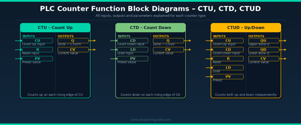
1. CTU Counter – Count Up (Most Used)
The CTU (Count Up) is the most widely used PLC counter instruction. It counts upward from 0 toward a preset value. When the accumulated count reaches the preset, the Q output activates.
How CTU Works
- Each rising edge on CU input → CV increments by 1
- When CV ≥ PV → Q output turns ON
- Counter continues counting above PV (does not stop at PV)
- Reset input (R) → CV resets to 0 → Q turns OFF
- Counter only counts on rising edge — not while input stays TRUE
CTU in Allen-Bradley Studio 5000
| Parameter | Tag | Example |
|---|---|---|
| Counter Tag | Bottle_Counter | COUNTER data type |
| Preset | Bottle_Counter.PRE | 100 (count 100 bottles) |
| Accum | Bottle_Counter.ACC | Current count 0–100+ |
| Done Bit | Bottle_Counter.DN | TRUE when ACC ≥ PRE |
| Count Enable | Bottle_Counter.CU | TRUE on each pulse |
CTU in Siemens TIA Portal
| Parameter | Tag | Example |
|---|---|---|
| Counter DB | “Bottle_CTU” | IEC_COUNTER instance DB |
| CU (Input) | %I0.0 | Photoelectric sensor signal |
| R (Reset) | %I0.1 | Reset push button |
| PV (Preset) | 100 | Count to 100 |
| Q (Done) | “Bottle_CTU”.Q | TRUE when CV ≥ 100 |
| CV (Current) | “Bottle_CTU”.CV | Current bottle count |
When to Use CTU
- Counting products on a conveyor
- Tracking machine cycles for maintenance scheduling
- Counting batch items before a packaging step
- Counting how many times an alarm has activated
- Production quantity tracking per shift
2. CTD Counter – Count Down
The CTD (Count Down) counter starts at a preset value and decrements toward zero. When CV reaches zero or below, the Q output activates. It is used when you need to track how many items or cycles remain rather than how many have occurred.
How CTD Works
- Load input (LD) → CV is loaded with PV value (initialized)
- Each rising edge on CD input → CV decrements by 1
- When CV ≤ 0 → Q output turns ON
- Counter continues decrementing below 0 (goes negative)
- Load input (LD) → CV reloads PV value and Q resets
When to Use CTD
- Remaining stock countdown on a production line
- Ingredient dispensing — count down remaining portions
- Displaying how many products remain before a changeover
- Counting down remaining cycles before maintenance
- Timer-based quota systems — count down from daily target
💡 CTD vs CTU Decision: Use CTU when you want to know “how many have been made” — use CTD when you want to know “how many are left”. Both provide the same information mathematically, but CTD makes the remaining count directly visible as the CV value without needing a subtraction calculation.
3. CTUD Counter – Up/Down Counter
The CTUD (Count Up/Down) counter combines CTU and CTD in a single function block. It has separate inputs for counting up (CU) and counting down (CD), sharing the same current value (CV). This makes it ideal for tracking quantities that both increase and decrease — such as warehouse stock levels or people in a room.
How CTUD Works
- Rising edge on CU → CV increments by 1
- Rising edge on CD → CV decrements by 1
- When CV ≥ PV → QU (upper output) turns ON
- When CV ≤ 0 → QD (lower output) turns ON
- Reset (R) → CV resets to 0
- Load (LD) → CV loads PV value
When to Use CTUD
- Warehouse stock tracking — items in (CU) and items out (CD)
- People counting in a building (enter = CU, exit = CD)
- Buffer fill level tracking (items added = CU, items removed = CD)
- Bidirectional conveyor product tracking
- Elevator floor position tracking
PLC Counter Types Comparison
| Feature | CTU | CTD | CTUD |
|---|---|---|---|
| IEC Name | CTU | CTD | CTUD |
| Rockwell Name | CTU | CTD | CTUD (via CTU+CTD) |
| Siemens Name | CTU | CTD | CTUD |
| Counts | Up from 0 | Down from PV | Up and down |
| Output ON when | CV ≥ PV | CV ≤ 0 | QU: CV≥PV / QD: CV≤0 |
| Reset input | R → CV = 0 | LD → CV = PV | R → CV = 0 |
| Best for | Production counting | Remaining count | Stock in/out tracking |
| Industry usage | ⭐⭐⭐⭐⭐ Most used | ⭐⭐⭐ Common | ⭐⭐⭐ Moderate |
7 Real PLC Counter Examples
Example 1 – Bottle Counting with Batch Reset (CTU)
Count 100 bottles on a filling line. When 100 are counted, stop the line and wait for operator acknowledgement before starting the next batch.
| Tag | Type | Description |
|---|---|---|
| BOTTLE_SENSOR | DI | Photoelectric sensor — detects each bottle |
| RESET_PB | DI | Operator reset push button |
| BOTTLE_CTU | CTU | Counter, PV = 100 |
| LINE_RUN | DO | Filling line motor output |
| BATCH_LAMP | DO | Batch complete indicator lamp |
Rung 1: BOTTLE_SENSOR (NO) → CTU Counter CU input (counts each bottle)
Rung 2: RESET_PB (NO) → CTU Counter R input (resets count to 0)
Rung 3: BOTTLE_CTU.Q (NC) → LINE_RUN output (line runs while count < 100)
Rung 4: BOTTLE_CTU.Q (NO) → BATCH_LAMP output (lamp ON when 100 reached)
Example 2 – Remaining Stock Countdown (CTD)
A production line starts with 500 blank labels. Each label used decrements the counter. When 50 labels remain, trigger a low-stock alarm so the operator can replenish.
Rung 1: LOAD_PB (NO) → CTD Counter LD input (loads 500 into CV)
Rung 2: LABEL_SENSOR (NO) → CTD Counter CD input (decrements each label used)
Rung 3: LABEL_CTD.Q (NO) → LOW_STOCK_ALARM output (Q activates when CV ≤ 0 which is 50 remaining when PV=50)
Example 3 – Maintenance Scheduling by Machine Cycles (CTU)
A hydraulic press requires lubrication every 10,000 press cycles. The CTU tracks total cycles and triggers a maintenance lamp when 10,000 is reached.
Rung 1: PRESS_SENSOR (NO) → CTU Counter, PV = 10000
Rung 2: MAINT_CTU.Q (NO) → MAINT_LAMP output
Rung 3: MAINT_RESET_PB (NO) → CTU Reset (R) input
Example 4 – Warehouse Stock Level Tracking (CTUD)
A warehouse conveyor feeds items into a buffer zone. Items enter from one end (increment) and exit from the other (decrement). CTUD tracks the exact number in the buffer at all times.
Rung 1: ENTRY_SENSOR (NO) → CTUD Counter CU input
Rung 2: EXIT_SENSOR (NO) → CTUD Counter CD input
Rung 3: CTUD.QU (NO) → BUFFER_FULL_ALARM (activates when buffer reaches max PV)
Rung 4: CTUD.QD (NO) → BUFFER_EMPTY_ALARM (activates when buffer reaches 0)
CV value is displayed on HMI screen showing current buffer count in real time.
Example 5 – Counter Combined with Timer (CTU + TON)
Count 50 products, then wait 30 seconds before allowing the next batch to start. This combines CTU and TON for a timed batch process.
Rung 1: PRODUCT_SENSOR (NO) → CTU Counter, PV = 50
Rung 2: BATCH_CTU.Q (NO) → TON Timer, PT = 30s (starts 30s delay after 50 counted)
Rung 3: BATCH_TIMER.Q (NO) → CTU Reset (R) — resets counter after 30s delay
Rung 4: BATCH_CTU.Q (NC) → CONV_RUN output (conveyor stops during wait)
Example 6 – Reject Counter with Production Ratio Alarm (CTU)
Count total products and rejected products separately. If rejected products exceed 5% of total, trigger a quality alarm.
Rung 1: PRODUCT_SENSOR (NO) → TOTAL_CTU (counts all products)
Rung 2: REJECT_SENSOR (NO) → REJECT_CTU (counts rejects only)
Rung 3: Use a comparison instruction — if REJECT_CTU.CV > (TOTAL_CTU.CV × 0.05) → QUALITY_ALARM output
Rung 4: SHIFT_END_PB (NO) → Reset both counters at end of shift
Example 7 – Multi-Stage Batch with Counter Cascade (CTU Chain)
A filling machine fills 3 stages: Stage 1 = 10 units, Stage 2 = 20 units, Stage 3 = 30 units. Each stage starts only after the previous is complete.
Rung 1: START_PB → STAGE1_CTU (PV=10) count input
Rung 2: STAGE1_CTU.Q (NO) → STAGE2_CTU (PV=20) count input
Rung 3: STAGE2_CTU.Q (NO) → STAGE3_CTU (PV=30) count input
Rung 4: STAGE3_CTU.Q (NO) → BATCH_COMPLETE lamp + reset all counters
High Speed Counters (HSC) – For Encoder Applications
Standard PLC counters process signals at the scan rate (1–20ms). For very fast pulses — such as encoder signals from motors and conveyors — the standard counter is too slow and will miss pulses.
High Speed Counter (HSC) modules are dedicated hardware modules that count pulses independently of the PLC scan cycle, at frequencies up to 1MHz or higher.
| Feature | Standard Counter | High Speed Counter |
|---|---|---|
| Max frequency | ~50Hz (limited by scan) | Up to 1MHz+ |
| Scan independent | No | Yes — hardware based |
| Used for | Products, cycles, events | Encoders, flow meters, speed |
| Siemens | CTU/CTD/CTUD | CTRL_HSC in TIA Portal |
| Allen-Bradley | CTU/CTD | HSC module with MAOC |
| Cost | Free — software only | Additional hardware module |
Common HSC applications: Motor encoder position tracking, flow meter pulse counting, conveyor speed measurement, rotary table positioning, CNC axis feedback.
PLC Counter Instructions by Brand
| Counter Type | Allen-Bradley | Siemens TIA Portal | Mitsubishi | Omron |
|---|---|---|---|---|
| Count Up | CTU | CTU | OUT C (K value) | CNT |
| Count Down | CTD | CTD | DECO C | CNTR |
| Up/Down | CTU + CTD (same tag) | CTUD | Not standard | Not standard |
| Done bit | .DN | .Q / .QU / .QD | C contact | C contact |
| Current value | .ACC | .CV | C current value | C current value |
| Preset value | .PRE | .PV | K value in program | Set value |
Common PLC Counter Mistakes
Mistake 1 – Forgetting to add a Reset rung
The most common counter mistake. If you never reset the counter, CV will keep incrementing past PV and the Q output stays permanently ON after the first batch. Always add a reset rung with a push button or automatic reset condition for every counter in your program.
Mistake 2 – Using the wrong input signal type
Counters only count on rising edges. If you connect a continuous ON signal (like a running motor status) to the CU input instead of a pulse signal, the counter will only count once — when that signal first goes TRUE. Always verify your counting signal produces a clean pulse for each event.
Mistake 3 – Duplicate counter addresses in legacy PLCs
In SLC 500 and older Allen-Bradley PLCs, using the same counter address (e.g., C5:0) in two different rungs will cause both rungs to control the same counter — producing unpredictable results. Each counter instruction must use a unique address.
Mistake 4 – Counter overflow on long-running systems
Counters have maximum values based on their data type — typically 32,767 for signed 16-bit integers or 2,147,483,647 for 32-bit integers. On a system that runs for years without reset, counters can overflow and wrap to negative values. Always implement automatic periodic resets for long-running counters tracking total production.
Mistake 5 – Not initializing CTD before use
A CTD counter must be loaded with its preset value (using the LD input) before it can count down meaningfully. If you forget the load rung, CV starts at 0 and immediately triggers the Q output. Always add an initialization rung that loads PV into CV when the program first starts.
Counters vs Timers — Key Differences
| Feature | Counter | Timer |
|---|---|---|
| What it counts | Events (rising edges) | Time (milliseconds) |
| Trigger | Each input pulse | Continuous input TRUE |
| Value type | Integer (number of events) | Time (ms, s, min) |
| Reset | Manual RES instruction required | Auto-resets when input goes FALSE |
| Used for | Products, cycles, events | Delays, run-on, intervals |
For a complete guide on PLC timers, read: PLC Timer – TON, TOF, RTO and TP Explained
Frequently Asked Questions – PLC Counter
What is a PLC counter?
A PLC counter is a software instruction that counts the number of times a specific input event occurs. Each time the input transitions from FALSE to TRUE (rising edge), the counter increments or decrements its accumulated value. When the accumulated value reaches the preset value, the counter output activates. PLC counters replaced mechanical counters in industrial control panels.
What is the difference between CTU and CTD counters?
CTU (Count Up) starts at zero and increments toward the preset value — its output activates when the count reaches the preset. CTD (Count Down) starts at the preset value and decrements toward zero — its output activates when the count reaches zero. Use CTU when tracking how many have been produced. Use CTD when tracking how many remain.
How do you reset a PLC counter?
In Allen-Bradley Studio 5000, add a separate rung with an RES (Reset) instruction using the same counter tag name — when the rung goes TRUE, the counter resets to zero. In Siemens TIA Portal, the R input of the CTU block resets CV to zero when it receives a TRUE signal. Always add a reset mechanism to every counter in your program, otherwise the counter will stay at its maximum value permanently.
What is a CTUD counter in PLC?
CTUD (Count Up/Down) is a counter that can both increment and decrement the same current value. It has separate CU (count up) and CD (count down) inputs. The QU output activates when CV reaches the upper preset, and the QD output activates when CV reaches zero. CTUD is used for tracking quantities that both increase and decrease, such as warehouse stock levels or buffer fill levels.
Can you use multiple counters in one PLC program?
Yes. Modern PLCs support hundreds or thousands of counter instructions in a single program. Each counter must have a unique tag name in Studio 5000 or a unique instance data block in TIA Portal. Large industrial programs commonly use dozens of counters — tracking products per line, cycles per machine, and rejects per shift simultaneously.
What is the difference between a counter and a timer in PLC?
A counter counts discrete events (rising edges on a digital input) and stores the result as an integer. A timer measures elapsed time and stores the result in time units (milliseconds or seconds). Counters are triggered by individual events like sensor pulses. Timers are triggered by a continuous TRUE condition and count while that condition remains active.
What is a high speed counter in PLC?
A high speed counter (HSC) is a dedicated hardware module that counts fast pulses independently of the PLC scan cycle. Standard counters are limited to signals slower than the scan rate (typically 50Hz maximum). HSC modules count at up to 1MHz or higher and are used for encoder signals, flow meters, and speed measurement applications.
How do you display a counter value on an HMI?
Connect the HMI display element to the counter current value tag — in Allen-Bradley this is CounterTag.ACC and in Siemens TIA Portal it is CounterDB.CV. The HMI reads this integer value directly from the PLC memory and displays it in real time. You can also use the counter value in math calculations — for example dividing by a shift duration to calculate production rate per hour.
Conclusion
PLC counters are essential in every industrial automation program. Mastering all three counter types — CTU, CTD, and CTUD — gives you the ability to track any event-based quantity in industrial systems.
To summarize when to use each:
- CTU — count up to a target: products made, cycles completed, alarms triggered
- CTD — count down from a target: remaining items, remaining cycles, stock levels
- CTUD — track a value that both increases and decreases: stock in/out, buffer levels
- HSC — count fast pulses from encoders, flow meters, and speed sensors
Related Guides:
- PLC Timer – TON, TOF, RTO and TP Complete Guide
- PLC Ladder Logic Tutorial – 7 Real Industrial Examples
- PLC Programming Languages – All 5 IEC 61131-3 Languages
- What Is a PLC? Complete Beginner’s Guide
Automation engineer based in Asia, with hands-on experience in PLC programming, SCADA, and industrial control systems across oil and gas, power, food and beverage, and water industries. Writes about PLC fundamentals, ladder logic, vendor-specific instruction sets for Siemens, Allen-Bradley, and other major platforms, and industrial communication protocols.