Last Updated: April 2026 | Written by automation engineers with real factory floor troubleshooting experience.
When a PLC stops on the factory floor, every minute of downtime costs money. Effective PLC troubleshooting requires a structured step-by-step approach — not random guessing. This complete PLC troubleshooting guide gives you that structure, covering every fault category from power supply failures to program logic errors, with specific steps for both Siemens S7-1200 and Allen-Bradley systems.
In this guide you will find:
- A proven 5-step PLC troubleshooting methodology used by experienced engineers
- Complete LED status indicator guide for Siemens and Allen-Bradley PLCs
- How to use the Siemens Diagnostic Buffer and Rockwell Fault Log
- Power supply, IO, communication and program fault troubleshooting — each with specific steps
- The most common PLC faults and their exact causes and fixes
- How to use online monitoring and force IO for live diagnosis
PLC Troubleshooting – The 5-Step Methodology
Experienced engineers follow a structured sequence when troubleshooting any PLC system. Jumping straight to the program or randomly swapping modules wastes time. Always work through these 5 steps in order:
| Step | Action | What You Are Looking For | Tools Needed |
|---|---|---|---|
| 1 | Check power supply | Correct voltage at PLC terminals, PSU status LED | Multimeter |
| 2 | Read LED status indicators | RUN/ERROR/MAINT LED pattern on CPU and modules | Eyes — no tools needed |
| 3 | Check IO modules and field wiring | Correct signals at input terminals, output activation | Multimeter, laptop |
| 4 | Open Diagnostic Buffer / Fault Log | Fault codes, timestamps, error descriptions | TIA Portal or Studio 5000 |
| 5 | Review program logic online | Rung states, data values, forced IO, incorrect logic | Laptop with PLC software |
💡 Golden Rule: Never make random changes to the PLC program while troubleshooting a live system. Document every change you make, test one change at a time, and always have a backup of the original program before editing anything.
PLC Troubleshooting – Step 1: Check the Power Supply
The majority of PLC failures that appear complex are actually simple power supply problems. Always check power first before doing anything else.
What to Check
| Check | Expected Value | If Wrong |
|---|---|---|
| 24VDC supply at PLC L+ and M terminals | 24V ±10% (21.6-26.4V) | Check PSU output, incoming AC supply, fuses |
| PSU OK LED | Solid green | Replace PSU if all inputs correct |
| Voltage under load | Must stay above 21.6V | PSU undersized — add capacity or replace |
| AC input to PSU | 100-240VAC (check nameplate) | Check incoming supply, circuit breaker, fuses |
| PLC CPU power connector | Seated firmly, no corrosion | Reseat or clean connector |
| 24VDC field supply (for sensors) | Separate 24VDC supply | Check if field PSU is separate from PLC PSU |
💡 Important: Always use a separate 24VDC power supply for field devices (sensors, solenoids) and a separate supply for the PLC CPU. Sharing one PSU for both is a common wiring mistake that causes erratic faults when field devices draw heavy current.
PLC Troubleshooting – Step 2: Read LED Status Indicators
PLC LED indicators are your fastest diagnosis tool — they give you the fault category instantly, before you even open the programming software. Learn to read them correctly.
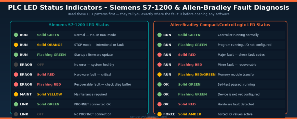
Siemens S7-1200 LED Status Guide
| LED | State | Meaning | Next Action |
|---|---|---|---|
| RUN | Solid GREEN | ✅ Normal — PLC in RUN mode | Check program logic — fault may be in logic |
| RUN | Solid ORANGE | ⚠️ STOP mode — intentional or fault | Check why CPU is in STOP — check diagnostic buffer |
| RUN | Flashing GREEN | ℹ️ Startup or firmware update in progress | Wait for startup to complete |
| ERROR | OFF | ✅ No error | Continue checking other areas |
| ERROR | Solid RED | 🔴 Hardware fault — serious | Check diagnostic buffer immediately |
| ERROR | Flashing RED | ⚠️ Recoverable fault — program or config | Open TIA Portal → Online & Diagnostics |
| MAINT | Solid YELLOW | ⚠️ Maintenance needed | Check diagnostic buffer for maintenance entry |
| LINK | Solid GREEN | ✅ PROFINET connected | Communication OK |
| LINK | OFF | ❌ No PROFINET connection | Check Ethernet cable, IP settings, switch |
Allen-Bradley CompactLogix / ControlLogix LED Guide
| LED | State | Meaning | Next Action |
|---|---|---|---|
| RUN | Solid GREEN | ✅ Controller running normally | Check program logic |
| RUN | Flashing GREEN | Program running, IO not fully configured | Check IO tree in Studio 5000 |
| RUN | Solid RED | 🔴 Major fault — controller faulted | Open Studio 5000 → Controller Properties → Faults |
| RUN | Flashing RED | ⚠️ Minor recoverable fault | Check fault log — may self-clear |
| OK | Solid GREEN | ✅ Self-test passed | Normal operation |
| OK | Solid RED | 🔴 Hardware fault detected | Replace module if fault persists after power cycle |
| FORCE | Solid AMBER | ⚠️ Forced IO values are active | Remove forces after troubleshooting |
| BAT | Solid RED | 🔋 Battery low or missing | Replace CPU battery — program may be lost on power cycle |
PLC Troubleshooting – Step 3: IO Faults
IO faults are the most common category of PLC problems. A sensor fails, a cable breaks, a module fails — the PLC either sees a wrong input state or cannot activate an output.
Digital Input (DI) Troubleshooting
| Symptom | Possible Cause | How to Test | Fix |
|---|---|---|---|
| Input always ON regardless of sensor | Wiring short to 24V, failed sensor | Disconnect sensor — if bit clears, sensor failed | Replace sensor or fix wiring |
| Input never turns ON | Open circuit, wrong wiring, failed module | Measure voltage at DI terminal with multimeter | Fix wiring or replace sensor/module |
| Input flickers erratically | Loose connection, electrical noise, wrong sensor type | Check all terminal screws, add shielding | Tighten connections, check NPN/PNP wiring |
| Wrong input activating | Cross-wiring, wrong terminal numbering | Trace cable from sensor to terminal | Correct wiring to right terminal |
Digital Output (DO) Troubleshooting
| Symptom | Possible Cause | How to Test | Fix |
|---|---|---|---|
| Output ON in program but device not activating | Blown output fuse, failed module channel | Force output ON — measure voltage at terminal | Replace fuse or module |
| Output always ON regardless of program | Failed transistor output (shorted), relay stuck | Force output OFF — if device stays ON, module failed | Replace IO module |
| Output activates intermittently | Loose wiring, overloaded output current | Check current draw vs module rating | Add intermediate relay for heavy loads |
| Device chatters (rapid ON/OFF) | Logic error, noisy input causing rapid output change | Go online and monitor rung conditions | Add timer or latch in logic to stabilize |
Analog Input (AI) Troubleshooting
| Symptom | Possible Cause | How to Test | Fix |
|---|---|---|---|
| Analog value reads 0 or minimum constantly | Wire break (4-20mA drops to 0mA), failed transmitter | Measure mA at AI terminals with clamp meter | Fix wiring, replace transmitter |
| Analog value reads maximum constantly | Short circuit on 0-10V, transmitter saturated | Disconnect transmitter — if value drops, transmitter failed | Replace transmitter |
| Analog value noisy/erratic | No shielded cable, cable routed near power cables | Replace with shielded twisted pair cable | Re-route cable, connect shield at panel end only |
| Wrong engineering units displayed | Incorrect scaling in program, wrong module config | Verify NORM_X/SCALE_X parameters (Siemens) or module scaling (AB) | Correct scaling parameters |
PLC Troubleshooting – Step 4: Using the Diagnostic Buffer
Siemens S7-1200 – TIA Portal Diagnostic Buffer
The Diagnostic Buffer is the most powerful built-in troubleshooting tool on the S7-1200. It stores a chronological log of all events, warnings, and faults with timestamps.
How to access:
- Open TIA Portal → Go Online (connect to PLC)
- In Project tree → right-click your CPU → “Online & Diagnostics”
- Click “Diagnostics” → “Diagnostic buffer”
- Read entries from newest (top) to oldest — the entry just before the STOP event is usually the cause
- Double-click any entry for full description and help text
| Common Diagnostic Buffer Entry | Meaning | Fix |
|---|---|---|
| Configuration error in rack/slot X | Hardware module missing or wrong type | Check physical module matches TIA Portal hardware config |
| I/O access error at address X | PLC trying to access IO that doesn’t exist | Check IO addresses in program match physical hardware config |
| Cycle time exceeded | Program scan taking longer than watchdog time | Optimize program loops, increase watchdog timeout in CPU properties |
| STOP caused by programming error | Divide by zero, array out of bounds, invalid pointer | Review OB error block — check math operations for divide by zero |
| Power supply fault | 24V supply voltage too low or too high | Measure supply voltage — check PSU and wiring |
| PROFINET device not reachable | IO device lost communication | Check Ethernet cable, device power, IP address settings |
Allen-Bradley – Studio 5000 Fault Log
How to access:
- Open Studio 5000 → Go Online
- Click Controller Properties (right-click controller in project tree)
- Click “Fault Log” tab — lists all major and minor faults with timestamps
- Note the fault code — use Rockwell’s Publication Library to look up the exact fault description
| Fault Type | Code Range | Typical Cause | Fix |
|---|---|---|---|
| I/O Fault | Type 3, Code 16 | IO module not responding | Check module power and connections |
| Program Fault | Type 4, Code 20 | Instruction execution error | Check program for math errors, array overruns |
| Motion Fault | Type 10 | Servo drive fault or configuration error | Check drive fault code, verify axis configuration |
| Watchdog Fault | Type 6, Code 1 | Scan time exceeded | Check for infinite loops, optimize program |
PLC Troubleshooting – Step 5: Program Logic Faults
Once hardware and IO are confirmed working, faults in the program logic are the next area to investigate. Go online in your programming software to monitor the program running in real time.
Online Monitoring Techniques
| Technique | How to Use | What It Reveals |
|---|---|---|
| Online Monitor (live rungs) | Go online in TIA Portal or Studio 5000 — rungs highlight green/grey showing live states | Exactly which contacts are open/closed, which coils are energized |
| Watch Table (TIA Portal) | Add tags to watch table — values update in real time | Live values of timers, counters, data block values, analog readings |
| Tag Monitor (Studio 5000) | Right-click tag → Monitor — shows live value | Current value of any tag in real time |
| Force IO | Force input or output ON/OFF to test logic without field device | Confirms whether logic responds correctly to forced condition |
| Cross Reference | TIA Portal: right-click tag → Cross reference. Shows every place a tag is used | Identifies all rungs that could be affecting a problem bit |
⚠️ Warning: Always remove all forced IO after troubleshooting. Leaving forces active on a live production system is extremely dangerous — a forced output can activate a motor or valve unexpectedly. TIA Portal shows a FORCE icon in the toolbar when any forces are active.
Common Program Logic Faults
| Symptom | Common Cause | How to Find It | Fix |
|---|---|---|---|
| Output never activates despite correct inputs | NC contact wired wrong, seal-in circuit missing | Go online — trace rung from left to right identifying which contact is open | Correct contact type or add seal-in |
| Output activates then immediately turns off | Interlock condition blocking output, timer too short | Go online — look for what turns the coil OFF | Fix interlock logic or adjust timer preset |
| Wrong output activates | Wrong tag assigned to output coil | Check coil address matches physical IO address | Correct tag assignment |
| Timer not reaching preset | Seal-in contact missing — timer resets before completing | Monitor timer ET (elapsed time) online | Add seal-in contact to hold timer input TRUE |
| Counter not incrementing | Input signal is continuous not pulsed, missing reset | Monitor CU input state online | Add rising-edge detection (P contact) |
| CPU goes to STOP during program | Divide by zero, accessing invalid DB, cycle time overrun | Check diagnostic buffer for exact error entry | Add zero-check before division, verify DB addresses |
PLC Communication Faults
Communication faults are increasingly common as PLC systems connect to more devices — HMIs, drives, remote IO, SCADA systems, and cloud platforms. Here is how to diagnose the most common types:
| Fault Type | Symptom | Check | Fix |
|---|---|---|---|
| PROFINET IO device offline | Red X on IO device in TIA Portal online view | Ping device IP from PC, check cable, check device power | Fix cable, restore power, verify IP address matches config |
| Cannot connect TIA Portal to PLC | “No compatible devices found” | PC and PLC on same subnet? Firewall blocking? Right network adapter selected? | Set PC IP to same subnet, disable Windows firewall temporarily |
| Modbus TCP timeout | MB_CLIENT error output active, status word error | Check IP address of Modbus server, check port 502 not blocked | Verify IP, check network route, increase timeout parameter |
| EtherNet/IP device offline (AB) | Yellow triangle on IO tree in Studio 5000 | Check device IP matches Studio 5000 config, check cable | Verify IP address, reset device, check EDS file |
| HMI not updating / connection lost | HMI shows “Connection Error” or stale values | Check HMI connection settings — IP address and slot number correct? | Verify HMI device table, check network cable, ping PLC from HMI |
PLC Troubleshooting Tools Every Engineer Needs
| Tool | Use | When to Use |
|---|---|---|
| Digital Multimeter | Measure voltage at IO terminals, check continuity | Always — first tool to pick up |
| Laptop with TIA Portal / Studio 5000 | Online monitoring, diagnostic buffer, force IO | After confirming hardware is correct |
| Clamp meter (4-20mA range) | Measure analog current loop without breaking circuit | Troubleshooting analog signal faults |
| Network cable tester | Verify Ethernet cable continuity and wiring | PROFINET / EtherNet/IP communication faults |
| Signal injector (4-20mA) | Inject known 4-20mA signal to test AI module | Isolating AI module vs transmitter faults |
| Laptop with Wireshark | Capture and analyze network packets | Complex communication faults, intermittent dropouts |
Frequently Asked Questions – PLC Troubleshooting
What is the first step in PLC troubleshooting?
The first step is always to check the power supply. Measure 24VDC at the PLC CPU terminals using a multimeter and verify the PSU status LED is green. The majority of PLC faults that appear complex are actually simple power supply problems — low voltage, blown fuses, or a failing PSU. Never skip the power check and go straight to the program.
What does a flashing red ERROR LED mean on a Siemens S7-1200?
A flashing red ERROR LED on the Siemens S7-1200 indicates a recoverable fault — typically a program logic error, communication timeout, or configuration mismatch. The CPU usually remains in RUN state but may have reduced functionality. Open TIA Portal, go online, and check the Diagnostic Buffer under Online and Diagnostics to read the exact fault code and description.
How do I access the diagnostic buffer on a Siemens S7-1200?
Connect TIA Portal to the S7-1200 online, then right-click the CPU in the project tree and select Online and Diagnostics. Click Diagnostics then Diagnostic Buffer. Read entries from newest to oldest — the entry immediately before any STOP event is typically the root cause of the fault. Double-click any entry for a full description and recommended corrective action.
How do I clear a major fault on an Allen-Bradley PLC?
In Studio 5000, go online and click Controller Properties then the Faults tab to read the fault description. After fixing the root cause, clear the fault by clicking the Clear Faults button in the controller properties, or by cycling power to the controller. Never clear a fault without first understanding and fixing the root cause — the fault will immediately return if the underlying problem is not resolved.
What causes a PLC to go to STOP mode unexpectedly?
The most common causes of unexpected PLC STOP are: a program error such as divide by zero or accessing an invalid memory address, a hardware configuration mismatch where a module in the program does not match the physical hardware, a cycle time watchdog timeout where the scan cycle takes longer than the configured maximum, or a power supply voltage dropping below the minimum threshold. Always check the Diagnostic Buffer or Fault Log immediately after an unexpected STOP to identify the exact cause.
How do I test a PLC output that is not working?
First confirm the output bit is TRUE in the program by going online and monitoring the output coil. If the bit is TRUE but the device is not activating, force the output ON using the Force IO function in TIA Portal or Studio 5000. Measure voltage at the output terminal with a multimeter — if voltage is present but the device does not activate, the fault is in the field wiring or the device itself. If no voltage is present despite the output being forced ON, the IO module channel has failed and needs replacing.
What is the most common cause of analog signal problems in PLC systems?
The most common cause of analog signal problems is incorrect cable installation — specifically using unshielded cable or routing analog cables alongside high-voltage power cables. Analog signals (4-20mA or 0-10V) are susceptible to electrical interference from motor drives, contactors, and fluorescent lighting. Always use shielded twisted-pair cable for analog wiring, connect the shield to earth ground at the panel end only, and route analog cables in separate cable trays from power cables.
How do I troubleshoot a PROFINET communication fault on S7-1200?
First check the physical connection — verify the Ethernet cable is undamaged and the LINK LED on both the PLC and the device are green. Then verify the device IP address matches exactly what is configured in TIA Portal — even one digit wrong will prevent communication. Try pinging the device IP from a laptop connected to the same network. If the device responds to ping but TIA Portal cannot connect, check that the device name in TIA Portal matches the PROFINET device name assigned to the physical hardware.
Conclusion
Effective PLC troubleshooting always follows the same structured path — power first, then LEDs, then IO, then diagnostic buffer, then program logic. Engineers who follow this sequence resolve faults faster and with less risk of making things worse.
Key rules to remember:
- Always check power first — most complex-looking faults have simple power causes
- Read LED indicators before opening any software — they tell you the fault category instantly
- Use the Diagnostic Buffer — it contains the exact fault description with timestamp
- Never make random changes — document every change, test one at a time
- Remove all forced IO after troubleshooting — leaving forces active is dangerous
- Back up the program before making any changes to a live system
Related Guides:
- Siemens S7-1200 Tutorial – Complete Beginner Guide
- PLC Inputs and Outputs – DI, DO, AI, AO Complete Guide
- PLC Ladder Logic Tutorial – 7 Real Industrial Examples
- What Is a PLC? Complete Beginner’s Guide
Automation engineer based in Asia, with hands-on experience in PLC programming, SCADA, and industrial control systems across oil and gas, power, food and beverage, and water industries. Writes about PLC fundamentals, ladder logic, vendor-specific instruction sets for Siemens, Allen-Bradley, and other major platforms, and industrial communication protocols.