Last Updated: April 2026 | Written for automation engineers and beginners learning PLC programming.
PLC ladder logic is the most widely used programming language in industrial automation. Whether you are a beginner starting your automation journey or an experienced engineer looking to solidify your fundamentals, this tutorial covers everything you need to know — from basic symbols to real industrial examples.
In this guide you will find:
- Every ladder logic symbol explained clearly with real usage examples
- 7 complete ladder logic examples from real industrial applications
- How ladder logic works in Siemens TIA Portal and Rockwell Studio 5000
- How to read ladder logic step-by-step — for total beginners
- A complete ladder logic symbols cheat sheet you can reference anytime
- The most common mistakes engineers make and how to avoid them
- A full comparison of ladder logic vs other PLC programming languages
⚡ Master Ladder Logic with Hands-On Exercises
Want to practice ladder logic with structured video lessons? The Ladder Logic PLC Programming for Beginners course on Udemy walks you through 25 hands-on examples and exercises — covering boolean logic, timers, counters, math operations, and finite state machines. Includes a free Ladder Logic Cheat Sheet bonus. Works with any PLC brand or simulator.
Disclosure: This is an affiliate link. We may earn a small commission at no extra cost to you, which helps support this free educational content.
What is PLC Ladder Logic?
Ladder logic (also called Ladder Diagram or LD) is a graphical programming language used to program Programmable Logic Controllers (PLCs). It represents control logic using symbols that resemble electrical relay circuits — with two vertical rails (power lines) and horizontal rungs connecting them, just like a physical ladder.
The name comes from the visual layout: each horizontal line of logic is called a rung, and multiple rungs stacked vertically form what looks like a ladder.
Ladder logic was originally developed to help electricians and technicians transition from hardwired relay panels to programmable controllers. Because it looks like a relay circuit diagram, anyone familiar with electrical schematics can read and understand it without needing traditional programming experience.
Today, ladder logic follows the international IEC 61131-3 standard, which defines programming languages for all PLC systems globally. It is supported by virtually every PLC manufacturer including Siemens, Allen-Bradley, Mitsubishi, Omron, and Schneider Electric.
Before writing ladder logic, make sure you understand how PLC inputs and outputs work — ladder logic directly controls these field signals.
Ladder Logic Basics — Core Concepts in 5 Minutes
Before diving into symbols and examples, here are the core ladder logic basics every beginner needs to understand. These five concepts make every ladder logic program — no matter how complex — easy to read once you know them.
1. Rails and rungs. Every ladder logic program has two vertical lines on the sides called rails — the left rail represents the power source, the right rail represents the return path. The horizontal lines connecting them are called rungs, and each rung contains one complete piece of control logic.
2. Inputs go on the left, outputs go on the right. Every rung reads like a sentence: the conditions (inputs) are on the left side, the action (output) is on the right side. If all the input conditions on the left are TRUE, the output on the right becomes ON.
3. Series connections are AND logic. Parallel connections are OR logic. When two contacts are placed in series (next to each other on the same line), both must be TRUE for the rung to activate the output — that is AND logic. When two contacts are placed in parallel (one above the other in a branch), either one can be TRUE to activate the output — that is OR logic. Almost every ladder logic program is built from combinations of these two patterns.
4. The PLC scans one rung at a time, top to bottom. The PLC does not execute all rungs at once. It reads input signals, executes rungs in order from top to bottom, then writes the outputs — and repeats. This cycle takes 1-20 milliseconds and is called the scan cycle.
5. Each output coil should appear only once. The most common ladder logic mistake is using the same output address (like Q0.0) on two different rungs. The PLC only honors the last rung — earlier rungs are silently ignored. One output, one rung. Always.
With these five ladder logic basics in mind, every example in this tutorial will make sense — even if you have never written a line of code before.
How Ladder Logic Works — The PLC Scan Cycle
Understanding how the PLC executes ladder logic is essential before writing your first program. The PLC does not run all rungs simultaneously — it processes them one at a time, top to bottom, in a repeating cycle called the scan cycle.
Each scan cycle has 4 stages:
| Stage | What Happens | Duration |
|---|---|---|
| 1. Input Scan | PLC reads all physical input signals (sensors, switches) | ~1ms |
| 2. Program Execution | PLC executes all ladder logic rungs top to bottom | ~1–10ms |
| 3. Output Scan | PLC writes all output states to physical devices | ~1ms |
| 4. Housekeeping | Communication, diagnostics, memory management | ~1ms |
The entire scan cycle typically completes in 1–20 milliseconds, repeating continuously while the PLC is in RUN mode. This is fast enough to respond to virtually any industrial process in real time.
Key rule: Each rung is evaluated left to right. If all input conditions on the left side of a rung are TRUE, the output on the right side is energized.
For a deep dive into how scan time affects program behavior, read our companion guide: PLC Scan Cycle Explained — How PLCs Read Inputs and Update Outputs.
How to Read Ladder Logic — Beginner’s Guide
Reading ladder logic feels intimidating the first time you see it, but it follows a simple pattern: left to right, top to bottom — exactly like reading English. Once you know what to look at first, every ladder logic diagram becomes readable in seconds.
Step 1 — Identify the Rails and Rungs
First, find the two vertical lines on the left and right side of the diagram — those are the rails. The horizontal lines connecting them are the rungs. Number them in your head from the top: Rung 1, Rung 2, Rung 3, and so on. The PLC reads them in this exact order, one at a time.
Step 2 — Read the Inputs on the Left
On every rung, the left side contains the input conditions. These look like contact symbols — either --[ ]-- (Normally Open, NO) or --[/]-- (Normally Closed, NC). Above each contact you will see a tag name like Start_PB or an address like I0.0. That tag tells you which physical input the contact is watching.
For each contact, ask one question: is this contact TRUE or FALSE right now? A Normally Open contact is TRUE when the input signal is ON. A Normally Closed contact is TRUE when the input signal is OFF.
Step 3 — Follow the Current Flow Left to Right
Imagine virtual current flowing from the left rail toward the right side of the rung. Current can only flow through contacts that are TRUE. If you hit a FALSE contact in series, the current stops there — the rung is broken and no output happens. If two contacts are in a parallel branch, the current only needs ONE path to be TRUE to keep flowing.
Step 4 — Identify the Output on the Right
The output appears on the right side of the rung — usually a coil symbol --( )-- with a tag name like Motor_Run. If the virtual current reached the coil, the output is ON. If the current was blocked anywhere on the left side, the output is OFF.
Step 5 — Move to the Next Rung
Once you have understood Rung 1, move down to Rung 2 and repeat. Outputs from earlier rungs are often used as inputs on later rungs — that is how the PLC chains logic together to build complex behaviour from simple rules. For more worked examples of reading rungs in plain English — including the seal-in, interlock, permissive, and latch patterns — see our dedicated How to Read Ladder Logic step-by-step guide.
💡 Reading Tip: When you are learning ladder logic, read each rung out loud as a sentence. For example, the classic motor start/stop rung reads as: “If Start is pressed OR the Motor is already running, AND Stop is NOT pressed, AND E-Stop is NOT pressed — then turn the Motor ON.” Translating ladder logic into plain English is the fastest way to build confidence.
PLC Ladder Logic Symbols — Complete Reference
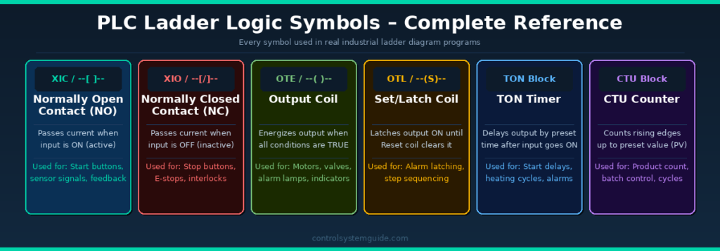
Every ladder logic program is built from a set of standard symbols. Here is every symbol you need to know:
1. Normally Open Contact (NO) — XIC
Symbol: --[ ]-- Rockwell: XIC Siemens: –| |–
A Normally Open contact passes current (evaluates TRUE) when the associated input signal is ON (active). When the input is OFF, no current passes.
Used for: Start push buttons, sensor signals, run feedback contacts, permissive conditions
Real example: Start push button — when pressed (ON), current flows through the rung and the motor output energizes.
2. Normally Closed Contact (NC) — XIO
Symbol: --[/]-- Rockwell: XIO Siemens: –|/|–
A Normally Closed contact passes current (evaluates TRUE) when the associated input signal is OFF (inactive). When the input turns ON, current stops — it blocks the rung.
Used for: Stop push buttons, emergency stops, safety interlocks, overload trips
Critical safety rule: Always use NC contacts for stop buttons and emergency stops. If the cable breaks, the NC contact opens and stops the machine — this is fail-safe behaviour.
3. Output Coil — OTE
Symbol: --( )-- Rockwell: OTE Siemens: –( )–
The Output Coil energizes a physical output device when all input conditions on the rung are TRUE. It de-energizes immediately when any input condition becomes FALSE.
Used for: Motor contactors, solenoid valves, alarm lamps, pilot lights, relay coils
4. Set Coil (Latch) — OTL
Symbol: --(S)-- Rockwell: OTL Siemens: –(S)–
The Set coil latches an output ON and keeps it ON even after the input condition goes FALSE. It stays ON until a Reset (OTU/R) coil on a separate rung clears it.
Used for: Alarm latching, step sequencers, mode selection, batch start/stop
5. Reset Coil (Unlatch) — OTU
Symbol: --(R)-- Rockwell: OTU Siemens: –(R)–
The Reset coil clears (turns OFF) a latched output that was previously set by a Set coil.
Used for: Alarm reset, batch stop, mode reset, step sequence return to start
6. TON Timer (On-Delay)
Symbol: Timer block Rockwell: TON Siemens: TON
The TON timer starts counting when the input condition becomes TRUE. After the preset time (PT) is reached, the timer output (Q) turns ON. If the input goes FALSE before the timer completes, it resets.
Used for: Motor start delays, alarm delays, heating cycle timing, conveyor dwell time. For complete timer coverage including TOF, RTO, and TP types, see our PLC Timer Guide.
7. TOF Timer (Off-Delay)
The TOF timer output turns ON immediately when the input goes TRUE. When the input goes FALSE, the timer starts counting — the output stays ON for the preset time then turns OFF.
Used for: Motor run-on after stop, cooling fan delays, lubrication systems
8. CTU Counter (Count Up)
Symbol: Counter block Rockwell: CTU Siemens: CTU
The CTU counter increments its accumulated value (ACC) by 1 each time the input has a rising edge (OFF to ON transition). When ACC reaches the preset value (PV), the counter output (Q/DN) turns ON.
Used for: Product counting, batch control, cycle counting, maintenance scheduling. For complete counter coverage including CTD and CTUD types, see our PLC Counter Guide.
Ladder Logic Symbols — Complete Cheat Sheet
Here is every ladder logic symbol you will encounter in real industrial PLC programs, organized into one quick-reference cheat sheet. The table shows the generic symbol, the Rockwell Allen-Bradley instruction, the Siemens TIA Portal instruction, and what each one does. For an even deeper symbol-by-symbol reference, see our dedicated Ladder Logic Symbols Guide.
| Symbol | Generic | Rockwell | Siemens | Function |
|---|---|---|---|---|
| NO Contact | --[ ]-- | XIC | –| |– | TRUE when input is ON |
| NC Contact | --[/]-- | XIO | –|/|– | TRUE when input is OFF |
| Output Coil | --( )-- | OTE | –( )– | Energize output when rung is TRUE |
| Set / Latch Coil | --(S)-- | OTL | –(S)– | Latch output ON (stays ON) |
| Reset / Unlatch Coil | --(R)-- | OTU | –(R)– | Clear a latched output |
| On-Delay Timer | Timer block | TON | TON | Output ON after preset delay |
| Off-Delay Timer | Timer block | TOF | TOF | Output OFF after preset delay |
| Retentive Timer | Timer block | RTO | (use TONR / IEC TON) | Accumulates time across resets |
| Pulse Timer | Timer block | (via TON) | TP | Output ON for fixed pulse time |
| Count-Up Counter | Counter block | CTU | CTU | Increments on rising edge |
| Count-Down Counter | Counter block | CTD | CTD | Decrements on rising edge |
| Up/Down Counter | Counter block | (CTU + CTD) | CTUD | Counts up and down |
| One-Shot Rising | --[ONS]-- | ONS | P trigger | TRUE for one scan on rising edge |
| Compare | --[EQU]-- | EQU, GEQ, LEQ, GRT, LES | ==, >=, <=, >, < | Compare two values |
| Math | Function block | ADD, SUB, MUL, DIV | ADD, SUB, MUL, DIV | Arithmetic operations |
| Move | Function block | MOV | MOVE | Copy data from source to destination |
Bookmark this ladder logic symbols cheat sheet for quick reference when reading or writing PLC programs. The generic symbols (column 2) work for any PLC platform — the Rockwell and Siemens columns let you map them to your specific vendor’s instruction set. For deeper coverage of each symbol with usage notes, common mistakes, and edge detection contacts, see our complete Ladder Logic Symbols Reference Guide.
7 PLC Ladder Logic Examples
These are the most common and important ladder logic examples used in real industrial automation systems. Each example explains the logic, the rungs, and the real-world application. For 20+ more examples covering motor control, timers, counters, conveyors, tanks, safety circuits, and traffic light sequencing, see our complete Ladder Logic Examples library.
Example 1 – Motor Start/Stop with Seal-In Contact
This is the most fundamental ladder logic program in industrial automation. It appears in virtually every factory that uses PLCs. Understanding this rung is the foundation of all ladder logic programming.
IO Used:
| Tag | Type | Address | Description |
|---|---|---|---|
| START_PB | DI | I0.0 | Start push button (NO contact) |
| STOP_PB | DI | I0.1 | Stop push button (NC contact) |
| MTR_RUN | DO | Q0.0 | Motor contactor output |
Rung 1 – Start/Stop Logic:
|--[START_PB]--+--[MTR_RUN]--[STOP_PB NC]--[E_STOP NC]--(MTR_RUN)--|
               |                                                      |
               +--[MTR_RUN]--+                                        |
How it works:
- When START_PB is pressed → current flows → MTR_RUN output energizes → motor starts
- MTR_RUN contact (seal-in) closes in parallel with START_PB → motor keeps running after button released
- When STOP_PB is pressed → NC contact opens → rung goes FALSE → motor stops
- If E_STOP activates → NC contact opens → motor stops immediately
💡 Engineering Note: The seal-in contact (also called a holding contact or latch) is one of the most important concepts in ladder logic. Without it, the motor would only run while the start button is held down. The seal-in keeps the circuit energized after the momentary button press is released.
Example 2 – TON Timer (Delayed Motor Start)
A 5-second delayed motor start — used in systems where a warning horn or light must sound before a machine starts. Common in conveyors, crushers, and processing equipment.
| Tag | Type | Address | Description |
|---|---|---|---|
| START_PB | DI | I0.0 | Start push button |
| TIMER_T1 | Internal | T1 | TON timer, preset 5 seconds |
| HORN | DO | Q0.1 | Warning horn output |
| MTR_RUN | DO | Q0.0 | Motor contactor output |
Rung 1: START_PB (NO) → TON Timer T1 (PT=5s)
Rung 2: START_PB (NO) → HORN output (warning sounds immediately)
Rung 3: T1.Q (timer done bit, NO) → MTR_RUN output (motor starts after 5s)
How it works: Start button pressed → horn sounds immediately → after 5 seconds → timer output goes TRUE → motor starts. This gives workers time to clear the area before the machine starts.
Example 3 – Conveyor with Product Detection
A conveyor that runs when a product is detected by a sensor and stops automatically when the product reaches the end position. Used in packaging, sorting, and material handling systems.
| Tag | Type | Address | Description |
|---|---|---|---|
| PHOTO_SENS | DI | I0.0 | Photoelectric sensor (product detected) |
| END_LIMIT | DI | I0.1 | End position limit switch |
| JAM_DETECT | DI | I0.2 | Belt jam detection sensor |
| CONV_RUN | DO | Q0.0 | Conveyor motor output |
| JAM_ALARM | DO | Q0.1 | Jam alarm indicator |
Rung 1: PHOTO_SENS (NO) + CONV_RUN seal-in → END_LIMIT (NC) → JAM_DETECT (NC) → CONV_RUN output
Rung 2: JAM_DETECT (NO) → JAM_ALARM output
How it works: Product detected → conveyor runs → seal-in holds it running → product reaches end limit → END_LIMIT opens → conveyor stops. If a jam occurs anytime → JAM_DETECT opens the main rung → conveyor stops → alarm activates.
Example 4 – Product Counter with Batch Reset
Counts products on a conveyor and stops the line after 100 units. Used in packaging, filling, and batch production systems.
| Tag | Type | Address | Description |
|---|---|---|---|
| SENSOR | DI | I0.0 | Product detection sensor |
| RESET_PB | DI | I0.1 | Counter reset push button |
| COUNTER_C1 | Internal | C1 | CTU counter, preset value 100 |
| LINE_RUN | DO | Q0.0 | Production line run output |
| BATCH_DONE | DO | Q0.1 | Batch complete indicator lamp |
Rung 1: SENSOR (NO) → CTU Counter C1 (PV=100) [count input]
Rung 2: RESET_PB (NO) → CTU Counter C1 [reset input]
Rung 3: C1.DN (counter done, NC) → LINE_RUN output (line stops when batch complete)
Rung 4: C1.DN (counter done, NO) → BATCH_DONE lamp (lights when batch complete)
Example 5 – Three-Motor Sequence Start
Motors must start in sequence: Motor 1 first, then Motor 2 five seconds later, then Motor 3 five seconds after that. Used in conveyor systems, processing lines, and pump stations.
| Tag | Type | Address | Description |
|---|---|---|---|
| START_PB | DI | I0.0 | System start button |
| STOP_PB | DI | I0.1 | System stop button (NC) |
| T1 | Timer | T1 | TON 5s — delay before Motor 2 |
| T2 | Timer | T2 | TON 5s — delay before Motor 3 |
| MTR1_RUN | DO | Q0.0 | Motor 1 contactor |
| MTR2_RUN | DO | Q0.1 | Motor 2 contactor |
| MTR3_RUN | DO | Q0.2 | Motor 3 contactor |
Rung 1: START_PB + MTR1_RUN seal-in → STOP_PB (NC) → MTR1_RUN (Motor 1 starts immediately)
Rung 2: MTR1_RUN (NO) → T1 Timer (5s delay)
Rung 3: T1.Q (NO) → MTR2_RUN (Motor 2 starts after 5s)
Rung 4: MTR2_RUN (NO) → T2 Timer (5s delay)
Rung 5: T2.Q (NO) → MTR3_RUN (Motor 3 starts after 10s total)
💡 Engineering Note: Sequential motor starts are essential in conveyor systems — you always start the last motor first (downstream) and the first motor last (upstream). This prevents product pile-ups. The ladder logic above starts upstream first, which is correct for a system where products flow Motor1 → Motor2 → Motor3.
Example 6 – Siemens TIA Portal Ladder Logic Format
Siemens uses a slightly different notation in TIA Portal. Here is the same motor start/stop circuit in Siemens format. For 12 more worked examples covering NO/NC contacts, output coils, Set/Reset latching, TON/TOF/TP timers, and CTU counters with Instance DBs, see our complete Siemens Ladder Logic Examples guide.
| Siemens Tag | Type | Address | TIA Portal Symbol |
|---|---|---|---|
| Start_PB | DI | %I0.0 | –| |– (NO contact) |
| Stop_PB | DI | %I0.1 | –|/|– (NC contact) |
| Motor_Run | DO | %Q0.0 | –( )– (output coil) |
| TON_T1 | Timer | DB1 | TON block (instance DB) |
💡 Siemens TIA Portal Note: In TIA Portal, all addresses use the % prefix (%I0.0, %Q0.0, %MW0). Timers and counters use Instance Data Blocks (IDB) — each timer or counter needs its own DB assigned in the program properties. This is different from Allen-Bradley where timers/counters use tag structures directly.
Example 7 – Allen-Bradley / Rockwell Studio 5000 Format
Rockwell Allen-Bradley uses tag-based ladder logic with specific instruction names. Here is the same motor control circuit in Studio 5000. For 12 more worked examples covering XIC, XIO, OTE, OTL, OTU, TON, CTU, and tag-based addressing patterns, see our complete Allen-Bradley Ladder Logic Examples guide.
| AB Tag Name | Type | Data Type | Instruction |
|---|---|---|---|
| Motor1_Start | DI | BOOL | XIC (Examine if Closed) |
| Motor1_Stop | DI | BOOL | XIO (Examine if Open) |
| Motor1_Run | DO | BOOL | OTE (Output Energize) |
| Motor1_Timer | Timer | TIMER | TON instruction |
| Motor1_Counter | Counter | COUNTER | CTU instruction |
💡 Rockwell Studio 5000 Note: Allen-Bradley uses XIC instead of NO contact and XIO instead of NC contact. OTE is the output coil. Timers in Studio 5000 use a TIMER data type tag with .PRE (preset), .ACC (accumulated), .DN (done bit) and .TT (timer timing bit) members. No fixed addresses — everything is tag-based.
Ladder Logic vs Other PLC Programming Languages
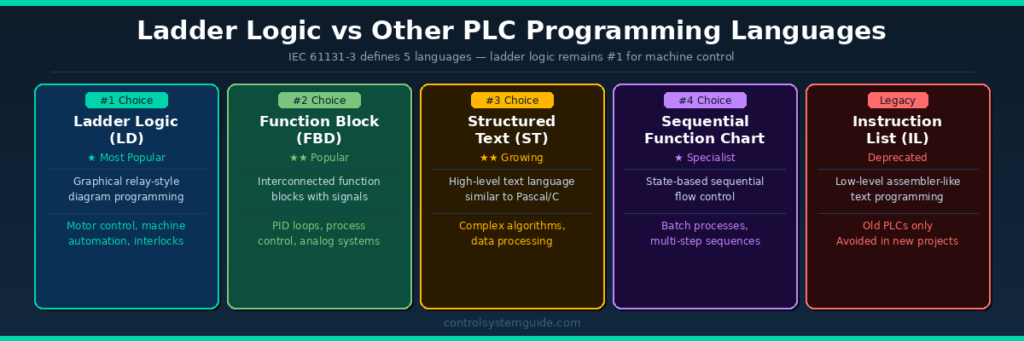
The IEC 61131-3 standard defines 5 PLC programming languages. Ladder logic is the most widely used, but each language has its strengths:
| Language | Best For | Difficulty | Used In |
|---|---|---|---|
| Ladder Logic (LD) | Machine control, discrete I/O | ⭐ Easiest | All industries |
| Function Block (FBD) | Process control, PID loops | ⭐⭐ Easy | Process industries |
| Structured Text (ST) | Complex algorithms, data | ⭐⭐⭐ Medium | Advanced projects |
| Sequential Function Chart (SFC) | Batch, multi-step sequences | ⭐⭐⭐ Medium | Batch processes |
| Instruction List (IL) | Legacy systems only | ⭐⭐⭐⭐ Hard | Old PLCs (deprecated) |
When to use Ladder Logic: Discrete machine control, motor control, conveyor systems, safety interlocks, basic process control — any application with ON/OFF inputs and outputs.
When to use other languages: Complex mathematical calculations (ST), modular process control (FBD), multi-step production sequences (SFC).
In practice, most modern PLC programs use a mix of languages — ladder logic for the main machine control, structured text for complex calculations, and function blocks for PID loops.
To learn about all 5 languages in detail, read: PLC Programming Languages Explained
Common Ladder Logic Programming Mistakes
These are the most frequent mistakes beginners and even experienced engineers make:
Mistake 1 – Using NO contact for Stop buttons
Stop buttons must always be NC contacts in ladder logic. If you use a NO contact for a stop button and the cable breaks, the button will stop working — the machine will keep running with no way to stop it. Always wire stop buttons as NC for fail-safe operation.
Mistake 2 – Forgetting the seal-in contact
Without a seal-in (holding) contact in parallel with the start button, the motor only runs while the start button is physically held down. Always add an auxiliary contact from the output coil in parallel with the momentary start input.
Mistake 3 – Double-coil programming
In a ladder logic program, each output coil address should only appear once. If you use Q0.0 as an output coil in two different rungs, only the last rung will control it — the first rung is ignored. This causes unpredictable behaviour and is one of the hardest bugs to find.
Mistake 4 – Missing emergency stop in every rung
Every rung that controls a potentially dangerous output (motors, hydraulics, valves) must include the emergency stop contact in series. A single E-stop rung at the start of the program is not enough in most safety applications.
Mistake 5 – No program comments or documentation
Ladder logic without rung comments and tag descriptions is extremely difficult to maintain. Always add a comment to every rung explaining what it does. Future engineers (and your future self) will thank you.
Mistake 6 – Incorrect timer/counter data types in Rockwell
In Studio 5000, if you assign the wrong data type to a timer tag (e.g., DINT instead of TIMER), the TON instruction will not work. Always verify your timer and counter tags use the correct data type (TIMER for TON/TOF, COUNTER for CTU/CTD).
Industrial Applications of PLC Ladder Logic
Ladder logic is used in virtually every industry that uses automated control systems:
| Industry | Typical Application | Key Ladder Logic Used |
|---|---|---|
| Manufacturing | Assembly line motor control | Start/stop, sequence, interlocks |
| Food & Beverage | Filling, capping, labelling machines | Counters, timers, conveyor control |
| Water Treatment | Pump control, level management | Analog comparison, timer delays |
| Oil & Gas | Valve sequencing, safety shutdown | Safety interlocks, latching, ESD |
| Automotive | Robotic welding, press control | Sequence, timers, safety monitoring |
| Packaging | Counting, wrapping, palletising | CTU counters, conveyor, reject gates |
| HVAC | AHU control, chiller sequencing | Timers, analog comparison, alarms |
| Power Generation | Generator control, load management | Interlocks, permissives, alarms |
Frequently Asked Questions – PLC Ladder Logic
What is ladder logic in PLC?
Ladder logic is a graphical programming language used to program PLCs. It represents control logic using symbols that resemble electrical relay circuits, arranged in horizontal lines called rungs between two vertical power rails — forming a shape that looks like a ladder. It is the most widely used PLC programming language in industrial automation worldwide.
Why is ladder logic called ladder logic?
Ladder logic gets its name from the visual appearance of the program. The diagram has two vertical lines (rails) representing power, with horizontal lines (rungs) connecting them — exactly like a physical ladder. Each rung contains one line of control logic.
Is ladder logic easy to learn?
Ladder logic is considered the easiest PLC programming language to learn, especially for people with an electrical background. The symbols look like familiar electrical relay symbols, and the logic follows a visual left-to-right, top-to-bottom pattern that is intuitive to read. Most beginners can write basic motor control programs within a few days of starting.
What is the difference between NO and NC contacts in ladder logic?
A Normally Open (NO) contact passes current when its associated input signal is ON. A Normally Closed (NC) contact passes current when its associated input signal is OFF — it blocks current when the signal turns ON. Start buttons use NO contacts. Stop buttons and emergency stops must always use NC contacts for fail-safe operation.
What is a seal-in contact in ladder logic?
A seal-in contact (also called a holding contact or latch) is an auxiliary contact from the output coil placed in parallel with the start button. It keeps the output energized after the momentary start button is released, so the motor continues running without holding the button. It is one of the most fundamental concepts in ladder logic programming.
What is the difference between ladder logic in Siemens TIA Portal and Allen-Bradley Studio 5000?
The core logic is the same, but the notation differs. Siemens uses | | for NO contacts, |/| for NC contacts, and % prefix for addresses (%I0.0, %Q0.0). Allen-Bradley uses XIC for NO contacts, XIO for NC contacts, and tag-based addressing with no fixed address numbers. Siemens timers use Instance Data Blocks while Allen-Bradley timers use TIMER data type tags.
What is the PLC scan cycle and why does it matter for ladder logic?
The scan cycle is the repeating process the PLC follows: read inputs → execute ladder logic → write outputs → housekeeping. It completes in 1–20 milliseconds and repeats continuously. Understanding the scan cycle matters because the PLC executes rungs sequentially — a change in one rung does not affect the current scan of rungs above it. It only takes effect in the next scan.
How many rungs can a ladder logic program have?
There is no fixed limit — modern PLCs can handle thousands of rungs. A small machine might have 20–50 rungs. A large industrial plant program can have thousands of rungs across multiple program blocks. Performance depends on the PLC CPU speed, but even entry-level PLCs can handle hundreds of rungs within a 10ms scan time.
Conclusion
PLC ladder logic is the foundation of industrial automation programming. From a simple motor start/stop circuit to complex sequential control systems, ladder logic provides a visual, reliable, and universally understood way to control machines and processes.
The key concepts to master are:
- NO and NC contacts and when to use each
- The seal-in contact for maintaining motor control
- Timers (TON, TOF) for time-based control
- Counters (CTU) for production tracking
- The PLC scan cycle and how it affects program execution
Start with the motor start/stop example, practice in PLC programming software with built-in simulators like Codesys or LogixPro, and build up to the more complex sequential examples. Ladder logic becomes intuitive with practice.
Related Guides:
- PLC Programming Languages Explained – LD, FBD, ST, SFC
- PLC Inputs and Outputs – DI, DO, AI, AO Explained
- Best PLC Software for Beginners – 10 Tools Reviewed
- Complete PLC Programming Guide – 23 Lessons
Automation engineer based in Asia, with hands-on experience in PLC programming, SCADA, and industrial control systems across oil and gas, power, food and beverage, and water industries. Writes about PLC fundamentals, ladder logic, vendor-specific instruction sets for Siemens, Allen-Bradley, and other major platforms, and industrial communication protocols.