Last Updated: May 2026 | A complete bookmarkable reference of every ladder logic symbol used in PLC programming.
Ladder logic symbols are the visual building blocks of every PLC program. If you can read these symbols, you can read any ladder logic program — regardless of the PLC brand, vendor, or industry. This complete reference covers every ladder logic symbol you will see in real industrial automation, including the generic IEC notation, the Allen-Bradley Rockwell instruction, and the Siemens TIA Portal equivalent.
In this guide you will learn:
- Every ladder logic symbol with what it looks like and what it does
- Side-by-side Rockwell vs Siemens vs generic IEC notation for each symbol
- Contact symbols — XIC, XIO, ONS and edge detection
- Coil symbols — OTE, OTL, OTU and when to use each
- Timer and counter symbols — TON, TOF, RTO, TP, CTU, CTD, CTUD
- Comparison, math, and move instruction symbols
- The most common symbol confusions that cause programming bugs
What Are Ladder Logic Symbols?
Ladder logic symbols are graphical instructions used to write PLC programs in the Ladder Diagram (LD) language. Each symbol represents either an input condition (a contact), an output action (a coil), or a function block (timer, counter, math instruction). They are arranged on horizontal lines called rungs, between two vertical power rails — forming a shape that looks like a ladder.
The symbols come from electrical relay schematics, which is why they look familiar to anyone who has worked with electrical control panels. The Normally Open contact looks like a pair of vertical bars, the Normally Closed contact has a diagonal slash through it, and the output coil looks like a circle or parentheses. The IEC 61131-3 international standard defines the modern symbol set used by every major PLC manufacturer worldwide.
Two notation systems dominate today. Allen-Bradley Rockwell uses mnemonic instruction names like XIC, XIO, OTE — common across North America. IEC 61131-3 uses the original graphical symbols and is more common in Europe and on Siemens TIA Portal. Both systems do exactly the same thing — they are just different names for the same logic.
If you are new to PLC programming, start with our complete PLC Ladder Logic Tutorial first, then return here as your symbol reference.
Ladder Logic Symbols Cheat Sheet — Complete Reference Table
Here is every ladder logic symbol you will encounter in industrial PLC programs, with the generic IEC notation, the Allen-Bradley Rockwell instruction, the Siemens TIA Portal equivalent, and a one-line description of what each symbol does. Bookmark this table — it is the fastest way to map between vendor notations in your daily work.
| Category | Symbol Name | Generic IEC | Rockwell | Siemens | What It Does |
|---|---|---|---|---|---|
| Contact | Normally Open | --| |-- | XIC | –| |– | TRUE when bit is ON |
| Contact | Normally Closed | --|/|-- | XIO | –|/|– | TRUE when bit is OFF |
| Contact | One-Shot Rising | --|P|-- | ONS | P trigger | TRUE for one scan on 0→1 edge |
| Contact | One-Shot Falling | --|N|-- | (via XIO+ONS) | N trigger | TRUE for one scan on 1→0 edge |
| Coil | Output Coil | --( )-- | OTE | –( )– | Energize output when rung is TRUE |
| Coil | Set / Latch | --(S)-- | OTL | –(S)– | Latch output ON, stays ON |
| Coil | Reset / Unlatch | --(R)-- | OTU | –(R)– | Clear a latched output |
| Timer | On-Delay | Timer block | TON | TON | Output ON after preset delay |
| Timer | Off-Delay | Timer block | TOF | TOF | Output OFF after preset delay |
| Timer | Retentive | Timer block | RTO | TONR / IEC TON retentive | Accumulates time across resets |
| Timer | Pulse | Timer block | (via TON) | TP | Output ON for fixed pulse width |
| Counter | Count Up | Counter block | CTU | CTU | Increments on rising edge |
| Counter | Count Down | Counter block | CTD | CTD | Decrements on rising edge |
| Counter | Up/Down | Counter block | CTU + CTD | CTUD | Counts up and down |
| Compare | Equal | --[ = ]-- | EQU | == / CMP | TRUE when value A = value B |
| Compare | Greater Than | --[ > ]-- | GRT | > | TRUE when value A > value B |
| Compare | Less Than | --[ < ]-- | LES | < | TRUE when value A < value B |
| Compare | Greater or Equal | --[ >= ]-- | GEQ | >= | TRUE when A is greater or equal to B |
| Compare | Less or Equal | --[ <= ]-- | LEQ | <= | TRUE when A is less than or equal to B |
| Math | Addition | Function block | ADD | ADD | Add two values, store result |
| Math | Subtraction | Function block | SUB | SUB | Subtract two values, store result |
| Math | Multiplication | Function block | MUL | MUL | Multiply two values, store result |
| Math | Division | Function block | DIV | DIV | Divide two values, store result |
| Data | Move | Function block | MOV | MOVE | Copy source value to destination |
| Branch | Jump to Label | --(JMP)-- | JMP / LBL | JMP / Label | Skip rungs based on condition |
| Branch | Subroutine Call | Function block | JSR | CALL | Execute another routine |
This cheat sheet covers every ladder logic symbol you will need for 99% of real industrial PLC programming work. The sections below explain each symbol category in detail with usage notes and common mistakes.
Contact Symbols in Ladder Logic
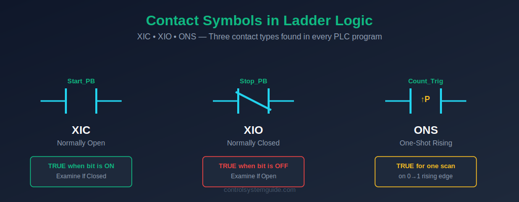
Contact symbols appear on the left side of every ladder logic rung. They represent input conditions that the PLC checks during each scan. Two contact types make up over 95% of all ladder logic — Normally Open (NO) and Normally Closed (NC) — with edge detection contacts adding specialized behavior for rising and falling signal transitions.
Normally Open Contact (NO) — XIC
Symbol: --| |-- Rockwell: XIC (Examine If Closed) Siemens: --| |--
The Normally Open contact passes virtual current — evaluates TRUE — when the referenced bit or input is ON (logic 1). When the bit is OFF, no current passes and the contact blocks the rung.
Important distinction: The Rockwell name “XIC” stands for Examine If Closed. This refers to checking if a tag is currently TRUE / ON, not the physical state of a relay contact. A start push button (Normally Open in hardware) sends a TRUE signal to the PLC when pressed — and an XIC contact watching that input evaluates TRUE.
Used for: Start push buttons, sensor signals, run feedback contacts, permissive conditions, internal logic bits, “is this ON?” checks.
Normally Closed Contact (NC) — XIO
Symbol: --|/|-- Rockwell: XIO (Examine If Open) Siemens: --|/|--
The Normally Closed contact passes virtual current — evaluates TRUE — when the referenced bit is OFF (logic 0). When the bit turns ON, the contact opens and blocks the rung. It is the logical inverse of the NO contact.
Used for: Stop push buttons, emergency stop circuits, safety interlocks, overload trip contacts, “is this OFF?” checks, fail-safe conditions.
⚠️ Critical safety rule: Stop buttons and emergency stops in the field are wired as Normally Closed in hardware — and read by an XIC (NO) contact in the program. If the cable breaks or the button fails, the input goes FALSE and the XIC evaluates FALSE — which stops the machine. This is fail-safe behavior. Never wire a stop button as Normally Open in the field.
One-Shot Rising (ONS) — Edge Detection
Symbol: --|ONS|-- Rockwell: ONS (One Shot) Siemens: P trigger / R_TRIG
The One-Shot Rising contact evaluates TRUE for exactly one PLC scan — the scan immediately after the input transitions from OFF to ON. On every subsequent scan, it returns FALSE until the input goes OFF and then back ON again.
Used for: Counter inputs that must increment exactly once per button press, single-fire actions, mode change triggers, edge-triggered initialization.
Without an ONS, holding down a button while the PLC is in a fast scan cycle would increment a counter many times — once per scan. The ONS ensures each press counts exactly once.
Coil Symbols in Ladder Logic
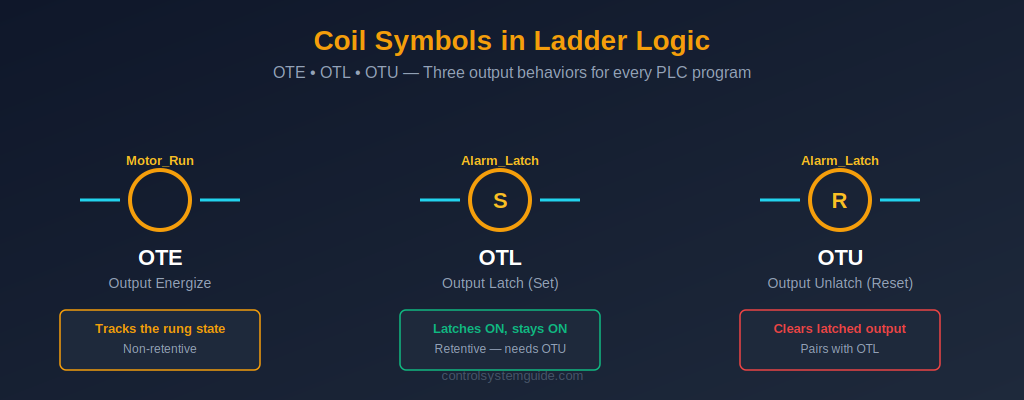
Coil symbols appear on the right side of every ladder logic rung. They represent the output action the PLC takes when all the input conditions on the left side of the rung are TRUE. Three coil types cover virtually all output behavior: the standard Output Coil (OTE), the Set / Latch coil (OTL), and the Reset / Unlatch coil (OTU).
Output Coil — OTE (Output Energize)
Symbol: --( )-- Rockwell: OTE Siemens: --( )--
The Output Coil energizes the referenced bit or output when all input conditions on the rung are TRUE. It de-energizes immediately when any input condition becomes FALSE. OTE is non-retentive — the bit state always tracks the rung state every scan.
Used for: Motor contactors, solenoid valves, alarm lamps, pilot lights, relay coils, indicator outputs, internal flag bits.
The OTE is the most common output symbol in any ladder logic program. In a typical motor control circuit, it drives a digital output that energizes the motor contactor. To understand how OTE outputs connect to real field devices, see our guide to PLC inputs and outputs.
Set Coil (Latch) — OTL (Output Latch)
Symbol: --(S)-- or --(L)-- Rockwell: OTL Siemens: --(S)--
The Set coil latches the referenced bit ON when the rung is TRUE — and keeps it ON even after the rung goes FALSE. It is retentive: once set, the bit stays ON across multiple scan cycles, surviving the input condition going away. The only way to turn it OFF is with a Reset (OTU) coil on a separate rung.
Used for: Alarm latching, step sequencers, mode selection bits, batch start/stop flags, fault history records, manual override flags.
Reset Coil (Unlatch) — OTU (Output Unlatch)
Symbol: --(R)-- or --(U)-- Rockwell: OTU Siemens: --(R)--
The Reset coil clears the referenced bit — turns it OFF — when the rung is TRUE. It is the partner instruction to OTL: every OTL needs a matching OTU somewhere in the program to clear the latch. If no OTU exists, the latched bit can only be cleared by a power cycle.
Used for: Alarm reset, batch complete clear, mode reset, step sequence return to start, fault acknowledgment.
💡 OTL and OTU rule: The Set and Reset coils for the same bit should appear in separate rungs with clear logic. If the Set rung and Reset rung are both TRUE at the same time, the Reset wins on the next scan — because the Reset is typically programmed below the Set, and the PLC executes top-to-bottom.
Timer Symbols in Ladder Logic
Timer symbols are function blocks that add time-based behavior to ladder logic. The IEC 61131-3 standard defines four timer types, each with a specific use case. Every modern PLC supports the on-delay timer (TON) at minimum; most also support off-delay (TOF), retentive (RTO), and pulse (TP) variants.
TON — On-Delay Timer
Rockwell: TON Siemens: TON (with Instance DB) Symbol: Timer function block with PT (preset), ET (elapsed), and Q (done output) terminals.
The TON timer starts counting when its input goes TRUE. After the preset time (PT) is reached, the timer’s done output (Q) turns ON. If the input goes FALSE before the timer completes, the elapsed time resets to zero. TON is the most common timer in industrial automation.
Used for: Motor start delays, warning horn duration before machine start, alarm debouncing, heating cycle timing, conveyor dwell times.
TOF — Off-Delay Timer
Rockwell: TOF Siemens: TOF (with Instance DB)
The TOF timer’s done output (Q) turns ON immediately when the input goes TRUE. When the input goes FALSE, the timer starts counting — the output stays ON for the preset time, then turns OFF. TOF is the mirror of TON.
Used for: Motor run-on after stop button (extract fans), cooling fan delays, lubrication systems that run after main motor stops, conveyor purge times.
RTO — Retentive On-Delay Timer
Rockwell: RTO Siemens: Use TON retentive mode or accumulating logic
The RTO timer behaves like TON, but it accumulates elapsed time across input transitions. If the input goes FALSE before the preset is reached, the elapsed time is preserved — and counting resumes from that value when the input goes TRUE again. The only way to clear an RTO is with a separate Reset (RES) instruction.
Used for: Total motor runtime tracking, total cycle time accumulation, maintenance schedule timers, equipment hours-of-operation logging.
TP — Pulse Timer
Rockwell: Implemented via TON logic Siemens: TP (native instruction)
The TP pulse timer generates a fixed-duration ON pulse on its output whenever the input rises from OFF to ON. The output stays ON for the preset time regardless of what the input does after that — even if the input drops back to OFF immediately.
Used for: Fixed-duration valve pulses, sample-and-hold operations, communication pulses, controlled-duration outputs from momentary inputs.
For complete timer coverage including timing diagrams, real examples, and Siemens vs Rockwell differences, see our dedicated PLC Timer Guide.
Counter Symbols in Ladder Logic
Counter symbols are function blocks that count rising-edge transitions on their input. They are essential for production counting, batch control, and any operation that requires a known number of events to trigger an action. Three counter types are defined in IEC 61131-3.
CTU — Count Up Counter
Rockwell: CTU Siemens: CTU Symbol: Counter function block with CU (count input), R (reset), PV (preset value), CV (current value), and Q (done) terminals.
The CTU counter increments its current value (CV) by 1 each time the count input (CU) has a rising edge — that is, transitions from OFF to ON. When CV reaches the preset value (PV), the done output (Q) turns ON. The counter holds the value until a reset signal clears it back to zero.
Used for: Product counting on conveyors, batch quantity control, cycle counting, maintenance cycle tracking, parts-per-shift logging.
CTD — Count Down Counter
Rockwell: CTD Siemens: CTD
The CTD counter decrements its current value (CV) by 1 each time the count input has a rising edge. It starts from a loaded preset value and counts down toward zero. When CV reaches zero, the done output turns ON.
Used for: Remaining quantity displays, countdown to batch completion, decrementing material inventory counters.
CTUD — Up/Down Counter
Rockwell: CTU + CTD combination Siemens: CTUD (single instruction)
The CTUD counter increments on the CU input and decrements on the CD input, giving you bidirectional counting. It has two done outputs — QU (TRUE when CV reaches PV) and QD (TRUE when CV reaches zero).
Used for: Parking lot space tracking, items in/out of warehouse, tank fill/empty cycles, real-time inventory counting.
For complete counter examples and Siemens vs Rockwell differences, see our dedicated PLC Counter Guide.
Comparison, Math, and Data Symbols
Beyond contacts, coils, timers, and counters, ladder logic includes a set of symbols for working with numerical values — comparing them, performing arithmetic, and moving them between memory locations.
Comparison Symbols — EQU, GRT, LES, GEQ, LEQ
Comparison instructions evaluate two values (often a process variable and a setpoint) and return TRUE when the comparison condition is satisfied. They appear in series with contacts on the left side of a rung.
- EQU (Equal): TRUE when value A equals value B
- GRT (Greater Than): TRUE when value A is greater than value B
- LES (Less Than): TRUE when value A is less than value B
- GEQ (Greater or Equal): TRUE when value A is greater than or equal to value B
- LEQ (Less or Equal): TRUE when value A is less than or equal to value B
Used for: Analog setpoint comparisons (tank level, temperature, pressure), batch quantity checks, alarm thresholds, recipe selection logic.
Math Symbols — ADD, SUB, MUL, DIV
Math instructions are function blocks that perform arithmetic on two source values and store the result in a destination tag. They execute every scan when the input rung is TRUE.
Used for: Engineering unit conversion (raw analog count to bar / °C / %), totalizer calculations, recipe scaling, batch quantity math.
MOV — Move Instruction
The Move instruction copies a value from a source tag to a destination tag. It executes every scan when the input rung is TRUE.
Used for: Loading setpoints from a recipe table, copying HMI input values to internal logic tags, initializing values on startup, transferring data between memory areas.
Common Ladder Logic Symbol Confusions
Even experienced engineers occasionally trip over these classic ladder logic symbol confusions. Knowing them in advance will save you debug time on real projects.
1. XIC vs Normally Open hardware contact. The XIC instruction looks like a Normally Open contact symbol, but it evaluates a tag’s TRUE/FALSE state — not the physical position of a relay contact. A field stop button wired Normally Closed in hardware still gets read by an XIC contact in the program. The XIC will be TRUE when the button is not pressed (cable intact, contact closed, input ON) and FALSE when pressed.
2. OTE vs OTL — when does the output stay ON? The OTE coil tracks the rung state every scan: rung TRUE = output ON, rung FALSE = output OFF. The OTL coil latches once and stays ON forever (or until an OTU clears it) — even if the rung goes FALSE. Mixing these up is the #1 source of “why did my output stay ON?” debugging sessions.
3. Double-coil mistake. If the same output address (for example Q0.0 or Motor_Run) appears as an OTE coil in two different rungs, only the second rung wins — the PLC silently ignores the first one. This is one of the hardest bugs to find. Rule: every output address gets exactly one OTE coil in the entire program.
4. Counter input without ONS. A CTU counter watching a button input increments once per scan as long as the button is pressed — not once per press. To get one increment per press, place an ONS contact in series with the count input, or use the button’s rising-edge as the trigger.
5. Latch without unlatch. Programming an OTL Set coil without a corresponding OTU Reset coil somewhere in the program creates a bit that can never be cleared — except by a power cycle. Always pair every Set with a Reset rung.
Frequently Asked Questions — Ladder Logic Symbols
What are the basic ladder logic symbols?
The basic ladder logic symbols are the Normally Open contact (XIC, –| |–), Normally Closed contact (XIO, –|/|–), and Output Coil (OTE, –( )–). Together these three symbols cover the majority of ladder logic in industrial automation. Add the Set / Latch coil (OTL), Reset / Unlatch coil (OTU), TON timer, and CTU counter to handle 95% of real-world PLC programming needs.
What is the difference between XIC and XIO in ladder logic?
XIC (Examine If Closed) is the Allen-Bradley name for a Normally Open contact — it evaluates TRUE when the referenced bit is ON. XIO (Examine If Open) is the Allen-Bradley name for a Normally Closed contact — it evaluates TRUE when the referenced bit is OFF. The names refer to the logical state being examined, not the physical state of a field relay contact. XIC and XIO are the inverse of each other.
What does OTE mean in ladder logic?
OTE stands for Output Energize. It is the standard output coil symbol in Allen-Bradley Rockwell ladder logic. The OTE coil energizes the referenced output bit when all input conditions on the rung are TRUE, and de-energizes the bit immediately when any input condition becomes FALSE. OTE is non-retentive — the output state always tracks the rung state every scan.
What is the difference between OTE, OTL, and OTU?
OTE (Output Energize) is non-retentive — the output is ON only while the rung is TRUE. OTL (Output Latch) is retentive — it sets the output ON and keeps it ON even after the rung goes FALSE. OTU (Output Unlatch) clears a latched output — it turns the bit OFF when its rung is TRUE. OTE is used for normal control outputs; OTL and OTU work as a pair for latching outputs like alarms and sequencer steps.
Are ladder logic symbols the same in Siemens and Allen-Bradley?
The visual symbols are the same — both Siemens TIA Portal and Allen-Bradley Studio 5000 use the IEC 61131-3 standard symbol shapes for contacts and coils. The instruction names differ: Allen-Bradley uses XIC, XIO, OTE, OTL, OTU; Siemens uses the graphical symbols without Allen-Bradley’s mnemonic names. Timers and counters work the same way logically, but Siemens requires Instance Data Blocks while Allen-Bradley uses TIMER and COUNTER data type tags.
Why does my OTE coil not turn on?
Three common reasons: (1) one of the input contacts on the rung is FALSE — trace each contact’s tag state in the PLC online monitor; (2) the same output address is used as an OTE in another rung below this one, which overwrites this rung’s value (double-coil mistake); or (3) the output module physical connection or PLC output configuration is incorrect. Always check the PLC online tag state before assuming the program logic is wrong.
Where can I find a ladder logic symbols PDF cheat sheet?
The complete ladder logic symbols reference table in this guide is the most up-to-date cheat sheet available — covering generic IEC notation, Allen-Bradley Rockwell, and Siemens TIA Portal equivalents in one table. Bookmark this page for daily reference, or copy the table into your engineering documentation.
Conclusion
Mastering ladder logic symbols is the fastest path to reading and writing any PLC program. The symbols are universal — XIC, XIO, OTE, OTL, OTU, TON, CTU, and the others mean the same thing in every PLC platform from Allen-Bradley to Siemens to Mitsubishi to Omron. Once you can recognize each symbol and what it does, every ladder logic diagram becomes readable.
Key takeaways:
- Contacts on the left, coils on the right — every rung follows this layout
- XIC = TRUE when ON; XIO = TRUE when OFF — the foundation of all logic
- OTE tracks the rung; OTL latches; OTU clears — three output behaviors
- Each output address gets only one OTE coil — never duplicate
- Pair every OTL Set with an OTU Reset — never strand a latched bit
Start by memorizing the top six symbols — NO, NC, OTE, OTL, OTU, and TON — then add the timer and counter variants as you encounter them on real projects. For deeper coverage of how these symbols come together into complete programs, see our PLC Ladder Logic Tutorial with 7 real industrial examples.
The international standard that defines all PLC programming symbols is IEC 61131-3, maintained by the International Electrotechnical Commission.
Related Guides:
- PLC Ladder Logic Tutorial – Symbols, Examples & How to Read
- PLC Timer Explained — TON, TOF, RTO, TP with 7 Examples
- PLC Counter Explained — CTU, CTD, CTUD with 7 Examples
- PLC Inputs and Outputs — DI, DO, AI, AO Explained
- PLC Scan Cycle Explained
Automation engineer based in Asia, with hands-on experience in PLC programming, SCADA, and industrial control systems across oil and gas, power, food and beverage, and water industries. Writes about PLC fundamentals, ladder logic, vendor-specific instruction sets for Siemens, Allen-Bradley, and other major platforms, and industrial communication protocols.