Last Updated: April 2026 | Written for automation engineers and beginners learning how PLCs work.
The PLC scan cycle is the fundamental operating mechanism of every Programmable Logic Controller. Every time a sensor changes state, every time a motor starts, every time a timer completes — it all happens because the PLC is continuously executing its scan cycle. Understanding the PLC scan cycle is essential for anyone learning PLC programming or troubleshooting PLC systems.
In this complete PLC scan cycle guide you will learn:
- What the PLC scan cycle is and the exact 4 phases it executes
- How the Input Image Table and Output Image Table work
- What scan time is — typical values and what affects it
- Why fast signals can be missed and how to handle them
- How scan cycle works in Siemens TIA Portal and Allen-Bradley Studio 5000
- How to monitor and optimize scan time in your PLC program
- What interrupt tasks are and when to use them
What Is the PLC Scan Cycle?
The PLC scan cycle is the continuous, repetitive process by which a PLC reads its inputs, executes the user program, updates its outputs, and performs internal housekeeping tasks — then immediately repeats the entire sequence again. This cycle runs continuously from the moment the PLC enters RUN mode until it is powered off or placed in STOP mode.
The scan cycle is what makes a PLC different from a standard computer running software. While a computer program runs once and stops, a PLC program runs in an infinite loop — scanning inputs and updating outputs continuously to maintain real-time control of the industrial process.
💡 Key Concept: The PLC scan cycle is not triggered by events — it runs continuously regardless of whether inputs change. Even when nothing in the process changes, the PLC is still scanning its inputs and re-executing the program dozens or hundreds of times per second.
According to the IEC 61131-3 standard for PLC programming, the scan cycle is the fundamental operating mechanism of all compliant controllers. To understand how a PLC uses these inputs and outputs in the scan cycle, read: PLC Inputs and Outputs – DI, DO, AI, AO Complete Guide
The 4 Phases of the PLC Scan Cycle
| Phase | Name | What Happens | Typical Duration |
|---|---|---|---|
| 1 | Input Scan | PLC reads all physical inputs and copies their states to the Input Image Table | 0.1 – 1ms |
| 2 | Program Execution | PLC executes the user program top-to-bottom using Input Image Table values | 1 – 15ms |
| 3 | Output Scan | PLC copies Output Image Table values to physical output terminals | 0.1 – 1ms |
| 4 | Housekeeping | Communications, diagnostics, timer/counter updates, memory management | 0.5 – 5ms |
PLC Scan Cycle Phase 1 – Input Scan
At the start of each scan cycle the PLC reads the current state of every connected physical input — digital inputs (ON/OFF), analog inputs (mA/V values), and any special function module inputs. These values are copied into a dedicated memory area called the Input Image Table (also called Input Process Image or Input Data Image depending on the PLC brand).
The Input Image Table
The Input Image Table is a snapshot of all input states at the moment the input scan ran. This snapshot is then used throughout the entire program execution phase — the PLC does not re-read the physical inputs during program execution.
| PLC Platform | Input Image Table Name | Address Example |
|---|---|---|
| Siemens S7-1200/1500 | Process Image Input (PII) | %I0.0, %IW64 |
| Allen-Bradley ControlLogix | Input Data Table | Local:1:I.Data.0 |
| Allen-Bradley SLC 500 | Input File (I:) | I:1/0 |
| Mitsubishi iQ-R | Input relay (X) | X0, X1, X2 |
| Omron NX/NJ | Input variables | Direct tag mapping |
💡 Critical Understanding: Because the PLC uses a snapshot of input states — not the live physical values — if a physical input changes state during the program execution phase, the PLC will NOT see that change until the next scan cycle. This is one of the most important concepts in PLC programming and is the source of many beginner confusion points.
PLC Scan Cycle Phase 2 – Program Execution
After capturing the input snapshot, the PLC executes the user program. In ladder logic, this means the PLC evaluates rungs from top to bottom, left to right — exactly like reading a page of text. Each rung is evaluated in sequence, one at a time.
How Program Execution Works
- Each rung is evaluated using the current values in the Input Image Table
- Contact instructions (NO, NC) read from the Input Image Table or internal memory
- Coil instructions write results to the Output Image Table or internal memory bits
- Internal memory bits (M bits, flags, markers) are updated immediately and available to subsequent rungs in the same scan
- Physical outputs are NOT updated until Phase 3 — they remain at their previous state throughout Phase 2
Top-to-Bottom Execution — Why Rung Order Matters
Because the PLC executes rungs sequentially from top to bottom, the order of rungs in your program affects behavior:
| Scenario | Effect | Recommendation |
|---|---|---|
| Coil in Rung 1 controls contact in Rung 2 | Rung 2 sees updated coil value in same scan | ✅ Normal — works as expected |
| Coil in Rung 10 controls contact in Rung 3 | Rung 3 uses OLD coil value — updated next scan | ⚠️ One scan delay — rearrange rungs if needed |
| Output coil used as input contact later | Works correctly — internal bits update immediately | ✅ Standard seal-in circuit technique |
PLC Scan Cycle Phase 3 – Output Scan
After program execution, the PLC copies the results from the Output Image Table to the physical output terminals. This is when field devices — motor contactors, solenoid valves, indicator lamps — are actually energized or de-energized.
The Output Image Table
Like the input side, PLC outputs use an Output Image Table as an intermediate memory buffer. During program execution, coil instructions write to this table — not directly to physical outputs. Only after the entire program has been executed does the PLC copy the Output Image Table to physical terminals in one batch update.
| PLC Platform | Output Image Table Name | Address Example |
|---|---|---|
| Siemens S7-1200/1500 | Process Image Output (PIQ) | %Q0.0, %QW64 |
| Allen-Bradley ControlLogix | Output Data Table | Local:1:O.Data.0 |
| Allen-Bradley SLC 500 | Output File (O:) | O:1/0 |
| Mitsubishi iQ-R | Output relay (Y) | Y0, Y1, Y2 |
PLC Scan Cycle Phase 4 – Housekeeping
The final phase of each scan cycle is housekeeping — internal tasks that keep the PLC system running correctly. These include:
| Housekeeping Task | Description |
|---|---|
| Communication processing | Exchange data with HMIs, SCADA, other PLCs, remote IO devices |
| Self-diagnostics | Check CPU health, memory integrity, module status |
| Watchdog timer reset | Reset the scan watchdog — if not reset, PLC goes to fault (proves scan is completing) |
| Timer/counter updates | Update accumulated values for hardware timers and counters |
| Memory management | Garbage collection, buffer management |
| Programming terminal service | Respond to online monitoring requests from TIA Portal or Studio 5000 For detailed scan cycle documentation see the Siemens S7-1200 System Manual — Chapter 9 covers CPU operating modes and scan cycle timing in full detail. |
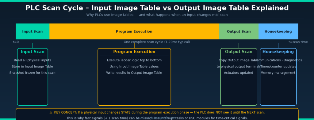
PLC Scan Cycle – Input Image Table vs Output Image Table
[UPLOAD IMAGE HERE: plc-scan-cycle-timing.png — Alt text: PLC scan cycle timing diagram input image table output image table explained]
What Is PLC Scan Time?
Scan time is the total time required for the PLC to complete one full scan cycle — all 4 phases. It is measured in milliseconds and is one of the most important performance parameters of a PLC system.
Typical Scan Times
| Application Type | Typical Scan Time | Examples |
|---|---|---|
| Simple programs — few IO | 0.5 – 2ms | Small conveyor, pump control, simple machine |
| Medium programs — moderate IO | 2 – 10ms | Packaging machine, filling line, HVAC control |
| Complex programs — heavy IO + comms | 10 – 50ms | Large process plant, many remote IO, PID loops |
| High-speed motion control | < 1ms | Servo positioning, high-speed cutting, robotics |
What Affects Scan Time
| Factor | Effect on Scan Time | Tip |
|---|---|---|
| Number of rungs / instructions | More rungs = longer scan | Remove unused rungs and dead code |
| Math and data manipulation | Complex math takes longer than bit logic | Use integer math where possible |
| Number of IO points | More IO = longer input/output scan | Use remote IO with high RPI only where needed |
| Communication tasks | Network comms add significant time | Use periodic tasks for non-critical comms |
| PID loops | Each PID loop adds processing time | Run PID in periodic task at fixed interval |
| CPU speed | Faster CPU = shorter scan time | Upgrade CPU if scan time is a bottleneck |
How to Monitor Scan Time
Siemens TIA Portal — S7-1200/1500
- Go online in TIA Portal
- Right-click your CPU → Online & Diagnostics
- Click Diagnostics → Cycle time
- View current, minimum, and maximum scan times
- Also visible in the CPU status display during online monitoring
Siemens also allows you to configure the maximum cycle time (watchdog) in CPU Properties → Cycle/Clock → Maximum cycle time. Default is 150ms — if exceeded the CPU goes to STOP.
Allen-Bradley Studio 5000 — ControlLogix / CompactLogix
- Go online in Studio 5000
- Click Controller Properties → Tasks
- Each task shows its current scan time
- Also accessible via the Controller Tags — system tag
S:FS(first scan bit) and task period settings - Use Controller Diagnostics for detailed timing breakdown
What Happens When an Input Changes Mid-Scan?
This is one of the most important concepts in PLC programming — and one that catches many beginners off guard.
Because the PLC takes a snapshot of inputs at the start of the scan (Phase 1) and uses that snapshot throughout program execution (Phase 2), any physical input that changes state DURING the program execution phase is NOT detected until the next scan cycle.
| Scenario | What Happens | Impact |
|---|---|---|
| Input changes at start of scan (before input scan) | ✅ Detected immediately — captured in this scan’s snapshot | Normal response — one scan delay |
| Input changes during program execution | ⚠️ NOT detected — missed until next scan | One full scan delay before response |
| Input pulse shorter than scan time | ❌ May be completely missed | Use HSC module or interrupt task |
| Very fast signal (encoder, pulse counter) | ❌ Will definitely be missed by standard IO | Must use High Speed Counter module |
⚠️ Critical Safety Note: For emergency stop signals and safety-critical inputs, always wire them directly to hardware safety relays or safety PLCs — never rely on the PLC scan cycle to detect safety events. The scan cycle delay (even 10-20ms) is too slow for machinery safety protection.
Interrupt Tasks — Responding Faster Than the Scan Cycle
When an application requires faster response than the standard scan cycle allows, PLCs support interrupt tasks — special program blocks that execute outside the normal scan cycle when triggered by a specific event.
| Interrupt Type | Trigger | Siemens TIA Portal | Allen-Bradley Studio 5000 | Use Case |
|---|---|---|---|---|
| Cyclic interrupt | Fixed time interval | OB30–OB38 (Cyclic OB) | Periodic Task | PID control, motion at fixed rate |
| Hardware interrupt | Rising/falling edge on input | OB40–OB47 (Hardware OB) | Event Task (Digital Input) | Emergency stop, fast counting |
| Time-of-day interrupt | Specific time/date | OB10–OB17 (TOD OB) | Not standard | Shift change, scheduled actions |
| Startup interrupt | PLC enters RUN mode | OB100 (Startup OB) | Not available | Initialization, default values |
PLC Scan Cycle in Siemens vs Allen-Bradley
| Feature | Siemens S7-1200/1500 | Allen-Bradley ControlLogix |
|---|---|---|
| Main program block | OB1 (Organization Block 1) | Continuous Task MainRoutine |
| Input image | Process Image Input (PII) — %I addresses | Input Data Table — Local:1:I tags |
| Output image | Process Image Output (PIQ) — %Q addresses | Output Data Table — Local:1:O tags |
| Cyclic interrupt | Cyclic OBs (OB30-OB38) | Periodic Tasks |
| Hardware interrupt | Hardware OBs (OB40-OB47) | Event Tasks |
| Scan time monitor | Online & Diagnostics → Cycle time | Controller Properties → Tasks |
| Watchdog timeout | CPU Properties → Max cycle time (default 150ms) | Task Properties → Period (continuous) |
| First scan detection | SM0.1 (first scan memory bit) | S:FS system bit |
How to Optimize PLC Scan Time
Tip 1 — Remove unused rungs and dead code
Every rung in the program is evaluated every scan — even rungs that are never TRUE. Remove any commented-out or unused ladder rungs. Unused code still consumes scan time.
Tip 2 — Move non-critical tasks to periodic tasks
Communication with HMIs, data logging, and report generation do not need to run every scan. Move them to periodic tasks with longer intervals (100ms, 500ms) to free up the main scan cycle.
Tip 3 — Use integer math instead of floating point where possible
Floating-point (REAL) arithmetic takes significantly longer to execute than integer (INT/DINT) arithmetic. Use integer scaling where precision allows.
Tip 4 — Avoid nested loops in structured text
FOR loops and WHILE loops in Structured Text (SCL/ST) that iterate many times will dramatically extend scan time. Always set a maximum iteration limit and verify that loops exit correctly.
Tip 5 — Optimize remote IO RPI settings
The Requested Packet Interval (RPI) on EtherNet/IP and PROFINET IO connections affects how often IO data is exchanged. Setting all remote IO to 1ms RPI when 10ms is sufficient wastes network bandwidth and CPU processing. Match RPI to the actual speed requirement of each device.
Tip 6 — Use event tasks for time-critical inputs
Instead of relying on the scan cycle to detect fast inputs, configure hardware interrupt tasks triggered directly by the input transition. This gives sub-millisecond response time regardless of scan cycle length.
Frequently Asked Questions – PLC Scan Cycle
What is the PLC scan cycle?
The PLC scan cycle is the continuous repetitive process by which a PLC operates. It consists of 4 phases executed in sequence: input scan (reading all physical inputs into the Input Image Table), program execution (running the user program top-to-bottom using the input snapshot), output scan (copying program results to physical output terminals), and housekeeping (communications, diagnostics, timer updates). This cycle repeats continuously while the PLC is in RUN mode.
What is a typical PLC scan time?
Typical PLC scan times range from under 1 millisecond for simple programs with few IO points, to 10-50 milliseconds for complex programs with many IO points, PID loops, and extensive network communications. Most standard industrial machine control programs run with scan times between 2 and 10 milliseconds. High-speed motion control applications may require scan times below 1 millisecond using dedicated motion controllers.
What is the Input Image Table in a PLC?
The Input Image Table is a memory area where the PLC stores a snapshot of all physical input states at the beginning of each scan cycle. During program execution the PLC reads from this table — not from the physical inputs directly. This means if a physical input changes state during program execution that change is not visible to the program until the next scan cycle when a fresh snapshot is taken.
Can a PLC miss an input signal?
Yes. If a physical input signal changes state and returns to its original state within the duration of one scan cycle the PLC may not detect it at all. This is because the PLC only snapshots inputs once per scan. For signals faster than the scan time — such as encoder pulses or very short switch activations — use a High Speed Counter module or configure a hardware interrupt task that responds directly to the input transition without waiting for the next scan cycle.
What happens when the PLC scan time exceeds the watchdog timeout?
Every PLC has a configurable watchdog timer that monitors the maximum allowed scan time. If a scan cycle takes longer than this limit the PLC assumes a program error has occurred and immediately goes to STOP mode to prevent uncontrolled machine behavior. On Siemens S7-1200 the default watchdog is 150 milliseconds. On Allen-Bradley ControlLogix it is configured per task. Always check the diagnostic buffer or fault log after a watchdog timeout to identify which part of the program caused the overrun.
What is the difference between a continuous task and a periodic task in PLCs?
A continuous task executes as fast as the PLC allows — completing each scan and immediately starting the next. The scan time varies depending on program complexity. A periodic task executes at a fixed time interval regardless of what else the PLC is doing — for example every 10 milliseconds exactly. Periodic tasks are ideal for PID control loops, motion control, and any function that requires consistent timing. Most modern PLCs support both task types simultaneously.
What is an interrupt task in PLC programming?
An interrupt task is a special program block that executes immediately when triggered by a specific event — bypassing the normal scan cycle. Hardware interrupts trigger when a digital input transitions from 0 to 1 or 1 to 0. Cyclic interrupts trigger at a precise fixed time interval. When an interrupt fires the current scan cycle is temporarily paused, the interrupt routine executes completely, and then the normal scan resumes from where it was paused. Interrupt tasks provide response times measured in microseconds rather than milliseconds.
How do I check scan time on a Siemens S7-1200?
Connect TIA Portal to the S7-1200 online then right-click the CPU in the project tree and select Online and Diagnostics. Click Diagnostics then Cycle time. This shows the current scan time, the minimum scan time recorded, and the maximum scan time recorded since the last CPU restart. The maximum value is the most important — it tells you the worst-case response time your program has experienced. If maximum scan time is approaching your watchdog limit consider optimizing the program.
Conclusion
The PLC scan cycle is the heartbeat of every industrial automation system. Every control action — every motor start, every valve open, every alarm trigger — happens as a result of the PLC completing scan cycles continuously and reliably.
Key points to remember:
- The scan cycle has 4 phases — Input Scan, Program Execution, Output Scan, Housekeeping
- The Input Image Table is a snapshot — physical inputs are NOT re-read during program execution
- If an input changes during program execution — it is not seen until the next scan
- Signals faster than the scan time may be missed — use HSC modules or interrupt tasks
- Scan time is typically 1-20ms for most industrial programs
- Use periodic and interrupt tasks for time-critical control functions
Related Guides:
- What Is a PLC? Complete Beginner’s Guide
- PLC Inputs and Outputs – DI, DO, AI, AO Complete Guide
- PLC Ladder Logic Tutorial – 7 Real Industrial Examples
- PLC Troubleshooting Guide – Step-by-Step Fault Finding
Automation engineer based in Asia, with hands-on experience in PLC programming, SCADA, and industrial control systems across oil and gas, power, food and beverage, and water industries. Writes about PLC fundamentals, ladder logic, vendor-specific instruction sets for Siemens, Allen-Bradley, and other major platforms, and industrial communication protocols.