Last Updated: April 2026 | Written for automation engineers, technicians and beginners learning industrial control systems.
PLC inputs and outputs are the connection between the PLC and the real world. Every sensor reading, every motor start, every valve movement — all of it passes through the PLC’s input and output modules. Understanding DI DO AI AO in PLC systems is the foundation of all PLC programming and automation engineering — and the first knowledge step every controls engineer must master.
This complete PLC inputs and outputs guide explains exactly what DI DO AI AO mean in PLC systems, how each signal type works, what field devices connect to each, and how to wire them correctly. By the end of this guide you will have full mastery of the four fundamental signal types used in every industrial automation project worldwide.
In this PLC inputs and outputs guide you will learn:
- Clear explanation of DI DO AI AO in PLC with real-world examples
- The 4 PLC input and output signal types with side-by-side comparison
- Full list of field devices connected to each PLC IO type
- Why 4-20mA is the industry standard analog signal — explained
- PLC digital output types — relay, transistor, triac — when to use each
- How PLC inputs and outputs are addressed in Siemens TIA Portal and Allen-Bradley Studio 5000
- How to wire DI DO AI AO in PLC systems correctly
- How to calculate PLC IO requirements for any project
- The most common PLC IO wiring mistakes and how to avoid them
What Are PLC Inputs and Outputs? – DI, DO, AI, AO Explained
PLC inputs and outputs are the communication interface between the programmable logic controller and the real-world industrial process. Inputs allow the PLC to receive signals from field devices like sensors and switches. Outputs allow the PLC to control machines and equipment like motors and valves. Together, the inputs and outputs enable the PLC to monitor process conditions and perform control actions based on the programmed logic.
The four fundamental PLC signal types — DI, DO, AI, and AO — represent the complete language of communication between a PLC and the physical world. Every push button, sensor, motor, valve, transmitter, and indicator lamp in an industrial system uses one of these four signal types to communicate with the PLC.
| Acronym | Full Name | Signal Type | Direction | Voltage / Format |
|---|---|---|---|---|
| DI | Digital Input | ON / OFF | Field → PLC | 24 VDC, 110 VAC, 230 VAC |
| DO | Digital Output | ON / OFF | PLC → Field | 24 VDC, 110 VAC, 230 VAC |
| AI | Analog Input | Variable signal | Field → PLC | 4-20 mA, 0-10 V, RTD, Thermocouple |
| AO | Analog Output | Variable signal | PLC → Field | 4-20 mA, 0-10 V |
PLC Inputs and Outputs — Quick Examples
To make DI DO AI AO in PLC easier to picture, here is one quick real-world example for each signal type from a typical industrial machine:
DI example: An operator presses the Start push button on the control panel — the 24 VDC signal from the button reaches a Digital Input on the PLC, which the program reads as “start request received.”
DO example: The PLC turns on a Digital Output that energizes a motor contactor coil — the motor starts running.
AI example: A pressure transmitter on the discharge pipe sends a 4-20 mA Analog Input signal — the PLC reads 12 mA and converts it to 5.0 bar inside the program.
AO example: The PLC sends a 4-20 mA Analog Output signal to the VFD speed reference — 12 mA tells the drive to run the motor at 50% of full speed.
These four examples — one push button, one motor contactor, one pressure transmitter, one VFD reference — cover the same four signal types found in every PLC project worldwide.
💡 Memory Trick for DI DO AI AO in PLC: Read the acronym from left to right.
The first letter tells you the signal nature — D for Digital, A for Analog.
The second letter tells you the direction — I for Input (PLC reads), O for Output (PLC writes).
DI DO AI AO in PLC – What Each Acronym Means
Every automation engineer must master the meaning of DI DO AI AO in PLC systems. These four acronyms are used in every PLC project document, IO list, P&ID drawing, and panel schedule worldwide. Understanding what they stand for and how they differ is the first step in industrial automation.
DI – Digital Input in PLC
DI in PLC stands for Digital Input — a signal coming from a field device to the PLC that has only two possible states: ON (logic 1) or OFF (logic 0). Digital inputs are the most common signal type in PLC systems and are used to monitor discrete events like push button presses, switch positions, and sensor states.
| DI Field Device | What It Tells the PLC | Common Voltage |
|---|---|---|
| Start push button | Operator pressed start | 24 VDC |
| Stop push button (NC) | Stop healthy / Stop pressed | 24 VDC |
| Emergency stop button | Safety circuit intact / E-stop pressed | 24 VDC |
| Limit switch | Mechanical position reached | 24 VDC |
| Proximity sensor | Metal object detected nearby | 24 VDC PNP/NPN |
| Photoelectric sensor | Object passed through beam | 24 VDC PNP/NPN |
| Float / level switch | Tank level reached high or low | 24 VDC |
| Pressure switch | Pressure exceeded setpoint | 24 VDC |
DO – Digital Output in PLC
DO in PLC stands for Digital Output — a signal sent from the PLC to a field device that switches the device ON or OFF. Digital outputs control motor contactors, solenoid valves, indicator lamps, and any device that operates in two states. The PLC determines when to activate each output based on the programmed control logic.
| DO Field Device | What the PLC Controls | Common Voltage |
|---|---|---|
| Motor contactor coil | Start / stop motor | 24 VDC or 230 VAC |
| Solenoid valve coil | Open / close pneumatic valve | 24 VDC typical |
| Indicator lamp | Show machine running status | 24 VDC |
| Tower lamp / beacon | Visual alarm signaling | 24 VDC |
| Alarm horn / siren | Audible alarm or warning | 24 VDC or 230 VAC |
| Relay coil | Switch high-current loads safely | 24 VDC |
| VFD enable signal | Enable variable frequency drive | 24 VDC |
| Heating element via SSR | Switch heater bank ON/OFF | 24 VDC to SSR control |
AI – Analog Input in PLC
AI in PLC stands for Analog Input — a continuously variable signal coming from a field transmitter to the PLC. Analog inputs let the PLC read real-world process variables like temperature, pressure, flow, level, and weight in proportional values rather than just ON/OFF states. The PLC’s internal Analog-to-Digital Converter (ADC) converts the variable signal into a numerical value (typically 12-bit or 16-bit) that the program can use.
| AI Field Device | What It Measures | Common Signal Format |
|---|---|---|
| Pressure transmitter | Pressure in bar, PSI, kPa | 4-20 mA |
| Temperature transmitter | Temperature in °C, °F | 4-20 mA |
| RTD direct connection | Temperature via Pt100 resistance | RTD 3-wire or 4-wire |
| Thermocouple direct | Temperature via mV signal | Thermocouple Type K, J, T |
| Flow meter | Flow rate in m³/h, L/min, GPM | 4-20 mA or pulse |
| Level transmitter | Tank level in % or meters | 4-20 mA |
| Load cell amplifier | Weight in kg, lb, tons | 4-20 mA or 0-10 V |
| VFD speed feedback | Motor actual speed | 4-20 mA |
| Position sensor / LVDT | Linear position in mm or % | 4-20 mA or 0-10 V |
AO – Analog Output in PLC
AO in PLC stands for Analog Output — a continuously variable signal sent from the PLC to a field device. Analog outputs control devices that need proportional control rather than just ON/OFF — for example modulating control valves, variable speed drives, and dosing pumps. The PLC’s internal Digital-to-Analog Converter (DAC) converts the program’s numerical output value into the physical 4-20 mA or 0-10 V signal sent to the field.
| AO Field Device | What the PLC Controls | Common Signal Format |
|---|---|---|
| Control valve positioner | Valve position 0-100% open | 4-20 mA |
| VFD speed reference | Motor speed in RPM or Hz | 4-20 mA or 0-10 V |
| Dosing pump speed | Chemical flow rate | 4-20 mA or pulse |
| Modulating damper actuator | HVAC airflow control | 0-10 V |
| SCR heater controller | Heating element power output | 4-20 mA |
| Servo drive position reference | Servo motor target position | ±10 V or digital network |
| Setpoint to remote controller | Process setpoint communication | 4-20 mA |
DI vs DO vs AI vs AO – Side by Side Comparison
This comparison table shows the key differences between all four PLC input and output signal types at a glance — useful for quick reference during PLC project design and IO list creation.
| Property | DI | DO | AI | AO |
|---|---|---|---|---|
| Full name | Digital Input | Digital Output | Analog Input | Analog Output |
| Signal type | ON/OFF | ON/OFF | Variable | Variable |
| Direction | Field → PLC | PLC → Field | Field → PLC | PLC → Field |
| Voltage / Format | 24 VDC, 110 VAC | 24 VDC, 110 VAC | 4-20 mA, 0-10 V | 4-20 mA, 0-10 V |
| PLC Resolution | 1 bit | 1 bit | 12-16 bit | 12-16 bit |
| Field example | Push button | Motor contactor | Pressure transmitter | Control valve |
| Cable type | 2-wire unshielded | 2-wire unshielded | Shielded twisted pair | Shielded twisted pair |
| Typical % of project IO | 40-60% | 20-30% | 10-20% | 3-10% |
| PLC module cost | Lowest | Low | Higher | Highest |
Difference Between DI and DO in PLC
The main difference between DI and DO in PLC is direction: DI sends ON/OFF signals from the field into the PLC, while DO sends ON/OFF signals from the PLC out to the field. A DI tells the PLC something happened — a button was pressed, a limit switch tripped, a level was reached. A DO tells the field to do something — energize a contactor, open a solenoid valve, light a lamp. Both are 1-bit binary signals, both typically use 24 VDC, and both wire with 2-wire unshielded cable. The PLC reads from DI and writes to DO.
Difference Between AI and AO in PLC
The difference between AI and AO in PLC is also direction, but for variable signals instead of ON/OFF. AI brings a continuously variable measurement into the PLC — pressure, temperature, flow, level, weight. AO sends a continuously variable command out from the PLC — control valve position, VFD speed reference, dosing pump rate. Both use 4-20 mA or 0-10 V signals and both require shielded twisted pair cable to prevent noise. The PLC’s ADC converts AI to a number the program can read; the PLC’s DAC converts a program number to the AO signal sent out.
Difference Between Digital and Analog Signals in PLC
The difference between digital and analog signals in PLC comes down to resolution and what they can represent. Digital signals (DI, DO) have only 2 states — ON or OFF — and use 1-bit resolution. They are perfect for switches, contactors, lamps, and any device that only needs two states. Analog signals (AI, AO) vary continuously across a range and use 12-bit or 16-bit resolution, giving 4,096 to 65,536 distinct values. They are needed for transmitters and modulating control devices that measure or control real-world process variables. Every industrial PLC project uses a mix of both — digital for discrete control, analog for proportional measurement and modulation.
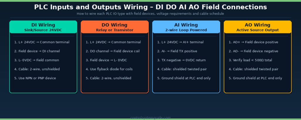
PLC Inputs and Outputs Wiring – Complete Field Connection Guide

Each of the 4 PLC IO types requires a specific wiring approach. Following the correct wiring for DI DO AI AO in PLC systems prevents the most common installation faults — and using shielded cable for analog signals is essential to avoid noise interference that distorts process measurements.
DI Wiring – PNP vs NPN Configuration
Digital input wiring uses either PNP (sourcing) or NPN (sinking) configuration depending on the field device. PNP is the European standard while NPN is more common in Asia. Most modern PLCs support both — selectable per channel via DIP switch or in the PLC software configuration.
| Configuration | How It Works | Common In |
|---|---|---|
| PNP (Sourcing) | Field device sources +24VDC to PLC input when active | Europe, North America, modern systems |
| NPN (Sinking) | Field device sinks 0VDC to PLC input when active | Asia, legacy systems, Japanese equipment |
| Dry contact | Simple switch between common and PLC input | Push buttons, limit switches, relay contacts |
DO Wiring – Relay, Transistor, and Triac Outputs
PLC digital outputs come in three main types — relay, transistor, and triac — each with different switching characteristics, response speeds, and load capacities. Choosing the correct DO type for your application prevents premature output failure.
| DO Type | Switching Speed | Load Capacity | Voltage | Best For |
|---|---|---|---|---|
| Relay output | 10 ms | Up to 2A | 24 VDC, 110 VAC, 230 VAC | General purpose, low frequency switching |
| Transistor (NPN/PNP) | 0.5 ms | Up to 0.5A | 24 VDC only | High-speed, frequent switching applications |
| Triac output | 10 ms (zero crossing) | Up to 1A | 110 VAC, 230 VAC | Direct AC load switching |
AI Wiring – 2-Wire vs 4-Wire Transmitters
Analog input wiring depends on whether the field transmitter is 2-wire (loop powered) or 4-wire (separately powered). 2-wire 4-20mA transmitters are by far the most common in process industry applications because they need only one shielded twisted pair carrying both power and signal.
| Transmitter Type | Wiring | Power Source | Common In |
|---|---|---|---|
| 2-wire loop powered | 2-wire shielded twisted pair | 24VDC supplied by PLC AI module | Pressure, temperature, level transmitters |
| 4-wire active | 2-wire signal + 2-wire power | Separate 24VDC field supply | Flow meters, complex instruments, mass flow |
| Voltage 0-10V | 2-wire shielded | Active or passive depending on device | HVAC sensors, OEM equipment |
AO Wiring – Active Source Output
Analog output wiring is always active source — the PLC supplies the 4-20mA current or 0-10V voltage signal directly to the field device. Always verify the total loop resistance of the receiving device is below the PLC AO module’s maximum specification (typically 500-750 ohms for 4-20mA).
Why 4-20 mA Is the Industry Standard for PLC Analog Inputs
The 4-20 mA analog signal is the global standard for PLC analog inputs and outputs in industrial automation. Almost every pressure transmitter, temperature transmitter, level transmitter, and control valve worldwide uses 4-20 mA — for several important technical reasons.
| Reason | Benefit |
|---|---|
| Built-in fault detection | Signal below 4 mA = broken wire, sensor failure, or power loss |
| Long cable distance | Current loops work reliably over 1000+ meters of cable |
| Noise immunity | Current signals less affected by electromagnetic interference than voltage |
| 2-wire loop power | Same 2 wires carry both 24VDC power and the 4-20 mA signal |
| Universal compatibility | Every major PLC brand and field device supports 4-20 mA natively |
| Industry safety standard | Required by ISA and IEC standards for process industries |
How a 4-20mA Signal Works in a PLC Input Loop
A 4-20mA signal works on a simple principle: the field transmitter regulates the exact amount of current flowing through the loop based on the value it is measuring. 4 mA represents 0% of the measurement range and 20 mA represents 100%. A pressure transmitter ranged 0-10 bar that is currently reading 5.0 bar will draw exactly 12 mA from the loop — halfway between 4 and 20 mA. The PLC analog input module measures this current and converts it to a numerical value the program can use.
The reason 4 mA represents “zero” instead of 0 mA is fault detection. If a wire breaks, the transmitter fails, or the loop power is lost, the current drops to 0 mA — which the PLC immediately recognizes as an out-of-range fault rather than confusing it with a legitimate zero reading. This is called live-zero signaling and is one of the main reasons 4-20mA replaced earlier 0-20mA and 0-10V standards in industrial automation. A 0-10V signal cannot distinguish “true zero” from “broken wire” — both look identical to the PLC.
For complete details on the 4-20 mA standard — including loop wiring, troubleshooting, signal conversion math, and HART protocol — read our companion guide: 4-20mA Signal Explained – Complete Industrial Guide.
How PLC Inputs and Outputs Are Addressed
Every PLC IO point has a unique address that the program uses to read or write the signal. Each major PLC platform uses different addressing conventions for DI DO AI AO in PLC programs.
Siemens TIA Portal Addressing
| Signal Type | Address Format | Example |
|---|---|---|
| Digital Input (DI) | %Ix.y or Ix.y | %I0.0, %I1.3 |
| Digital Output (DO) | %Qx.y or Qx.y | %Q0.0, %Q1.3 |
| Analog Input (AI) | %IWx | %IW64, %IW66 |
| Analog Output (AO) | %QWx | %QW80, %QW82 |
Allen-Bradley Studio 5000 Addressing
| Signal Type | Address Format | Example |
|---|---|---|
| Digital Input (DI) | Local:Slot:I.Data.Channel | Local:1:I.Data.0 |
| Digital Output (DO) | Local:Slot:O.Data.Channel | Local:2:O.Data.3 |
| Analog Input (AI) | Local:Slot:I.Ch0Data | Local:3:I.Ch0Data |
| Analog Output (AO) | Local:Slot:O.Ch0Data | Local:4:O.Ch0Data |
Allen-Bradley uses tag-based addressing — each address is mapped to a descriptive tag name like Start_Button or Tank_Level. Read our complete Allen-Bradley PLC Programming Guide for tag-based programming details.
To work with these addressing formats, you’ll need the right development environment — see our comparison of free and paid PLC programming software covering both Siemens TIA Portal and Studio 5000.
How to Calculate PLC Inputs and Outputs Required for a Project
Calculating the total IO count is the first step in selecting the right PLC for any project. Follow this 5-step process to determine your PLC inputs and outputs requirement accurately.
| Step | Action | Result |
|---|---|---|
| 1 | List every sensor and switch — these become DI signals | Total DI count |
| 2 | List every actuator, motor, lamp — these become DO signals | Total DO count |
| 3 | List every transmitter and analog instrument — these become AI signals | Total AI count |
| 4 | List every modulating control device — these become AO signals | Total AO count |
| 5 | Add 20-25% spare capacity to each total for future expansion | Final IO count for PLC sizing |
For complete worked examples and the free Excel template for IO calculation, read: PLC I/O Count Calculation – Step-by-Step Method with Excel Template
Common PLC IO Wiring Mistakes
| Mistake | Why It Matters | How to Avoid |
|---|---|---|
| Mixing AC and DC on same module | Damages the PLC module immediately | Use separate modules for 24VDC and 110/230VAC signals |
| No flyback diode on DC relay coils | Voltage spike damages transistor outputs | Always install reverse-biased diode across coils |
| Grounding analog shield at both ends | Creates ground loop — adds noise to signals | Ground shield at PLC end ONLY, leave field end open |
| Exceeding AO loop resistance limit | Output cannot drive 20mA — readings stuck at 12mA | Verify total load < 500Ω before commissioning |
| Mixing PNP and NPN inputs randomly | Confusing wiring, intermittent faults | Standardize on one configuration per project |
| Wiring multiple devices in series | Cannot identify which device caused a fault | Each field device gets its own dedicated PLC IO point |
| Forgetting interrogation voltage source | Inputs do not energize — system appears dead | Verify common terminal connected to L+ or L- correctly |
PLC Input Devices and Output Devices — Complete List
PLC input devices are field devices that send signals to the PLC. PLC output devices are field devices the PLC sends signals to. Knowing exactly which category each device belongs to is essential when building an IO list, sizing a panel, and selecting the right PLC modules for a project. The two tables below cover every common PLC input device and PLC output device found in industrial automation.
PLC Input Devices
Every PLC input device either sends a digital ON/OFF state (DI) or a variable analog measurement (AI). The table below shows the most common PLC input devices and which signal type each one produces.
| PLC Input Device | Signal Type | What It Tells the PLC |
|---|---|---|
| Push button (NO/NC) | DI | Operator command — start, stop, reset |
| Selector switch | DI | Mode selection — manual, auto, off |
| Emergency stop button | DI | Safety circuit healthy / E-stop pressed |
| Limit switch | DI | Mechanical position reached |
| Proximity sensor | DI | Metal or plastic object detected |
| Photoelectric sensor | DI | Object passed through light beam |
| Float / level switch | DI | High or low tank level reached |
| Pressure switch | DI | Pressure setpoint reached |
| Temperature switch / thermostat | DI | Temperature setpoint reached |
| Pressure transmitter | AI | Actual pressure value in bar / PSI / kPa |
| Temperature transmitter / RTD / thermocouple | AI | Actual temperature in °C / °F |
| Flow meter | AI | Flow rate in m³/h, L/min, GPM |
| Level transmitter | AI | Tank level in % or meters |
| Load cell / weight transmitter | AI | Weight in kg or tons |
| VFD speed feedback | AI | Motor actual running speed |
PLC Output Devices
Every PLC output device receives either a digital ON/OFF command (DO) or a variable analog command (AO). The table below shows the most common PLC output devices and which signal type each one accepts.
| PLC Output Device | Signal Type | What the PLC Controls |
|---|---|---|
| Motor contactor coil | DO | Start / stop motor |
| Solenoid valve coil | DO | Open / close pneumatic or hydraulic valve |
| Indicator lamp | DO | Show machine running, fault, or status |
| Tower lamp / beacon | DO | Visual alarm signaling |
| Alarm horn / siren | DO | Audible alarm or warning |
| Relay coil | DO | Switch high-current loads safely |
| VFD enable input | DO | Enable variable frequency drive |
| SSR heater control | DO | Switch heater bank ON / OFF |
| Control valve positioner | AO | Valve position 0-100% open |
| VFD speed reference | AO | Motor speed in RPM or Hz |
| Dosing pump speed reference | AO | Chemical flow rate |
| Modulating damper actuator | AO | HVAC airflow control |
| SCR / proportional heater controller | AO | Heating element power output |
| Servo drive position reference | AO | Servo motor target position |
In a typical industrial automation project, around 40-60% of total IO points are DI from input devices, 20-30% are DO to output devices, 10-20% are AI from transmitters, and 3-10% are AO to modulating control devices. Knowing this split helps estimate module quantities and panel size early in the design phase.
PLC Inputs and Outputs Module Types
PLC IO modules come in different physical configurations depending on the PLC family and project size:
| Module Type | Typical Channels | Used In |
|---|---|---|
| Compact integrated IO | 10-40 channels built into CPU | Compact PLCs — Siemens S7-1200, Allen Bradley Micro850 |
| Local expansion modules | 8, 16, 32 channels per module | Compact PLCs — connected directly to CPU |
| Rack-based modules | 16, 32, 64 channels per module | Modular PLCs — Siemens S7-1500, ControlLogix |
| Distributed remote IO | Variable — connected via network | Large plants — ET 200SP, Point IO over EtherNet/IP or PROFINET |
| IO-Link modules | 4-8 IO-Link masters | Smart sensors and actuators with bidirectional data |
According to the International Society of Automation (ISA) — the global standards body for industrial automation — distributed remote IO architectures using PROFINET or EtherNet/IP are now the dominant choice for new automation projects above 200 IO points.
Frequently Asked Questions – PLC Inputs and Outputs
What does DI DO AI AO mean in PLC?
DI DO AI AO in PLC stands for the four fundamental signal types used in industrial automation. DI is Digital Input — an ON/OFF signal from a field device to the PLC. DO is Digital Output — an ON/OFF signal from the PLC to a field device. AI is Analog Input — a continuously variable signal from a transmitter to the PLC. AO is Analog Output — a continuously variable signal from the PLC to a control device. Together these four signal types cover every possible communication between a PLC and field equipment in industrial automation.
What is the difference between DI and AI in PLC?
DI (Digital Input) reads only two states from a field device — ON or OFF — typically at 24VDC voltage. AI (Analog Input) reads a continuously variable signal — typically 4-20 mA or 0-10 V — that represents a real measurement value like temperature, pressure, or flow. DI is used for switches, push buttons, and proximity sensors. AI is used for transmitters that measure variable process conditions. Both DI and AI carry information from the field to the PLC but DI is binary while AI is proportional.
What is the difference between DO and AO in PLC?
DO (Digital Output) sends an ON/OFF signal from the PLC to a field device that operates in two states — for example a motor contactor or solenoid valve. AO (Analog Output) sends a continuously variable signal from the PLC to a device that needs proportional control — for example a control valve positioner or VFD speed reference. DO uses 24VDC or 110-230VAC switching. AO uses 4-20 mA or 0-10 V variable signals. Both carry signals from the PLC to the field but DO is binary while AO is proportional.
What is the difference between digital and analog signals in PLC?
Digital signals in PLC have only two possible states — ON or OFF — making them simple and reliable for binary conditions like switch positions and motor states. Analog signals vary continuously over a range of values — making them suitable for measuring real-world variables like temperature, pressure, flow, and level. Digital signals use 1-bit resolution. Analog signals use 12-bit or 16-bit resolution providing 4096 to 65,536 distinct values. Both signal types are essential — digital for discrete control and analog for proportional measurement and modulation.
Why is 4-20 mA used for analog inputs in PLC?
4-20 mA is the global standard for PLC analog inputs because it provides built-in fault detection (signal below 4 mA indicates broken wire), works reliably over 1000+ meters of cable, has excellent immunity to electrical noise, supports 2-wire loop powering (same wires carry power and signal), and is universally compatible across all major PLC brands and field instruments. Safety-rated process industries require 4-20 mA per ISA and IEC standards.
How many PLC inputs and outputs does a project need?
The number of PLC inputs and outputs depends on the project size. Small machines need 10-30 IO points. Medium machines need 30-100 IO. Production lines need 100-500 IO. Large plants need 500-2000 IO. Plant-wide systems exceed 2000 IO. Always add 20-25% spare capacity to the calculated total for future expansion. For detailed calculation methods read our PLC IO Calculation guide.
What are PLC input and output modules?
PLC input and output modules are the physical hardware that connects field devices to the PLC. They convert real-world signals into the digital data the PLC processor can read. Input modules accept signals from sensors and switches. Output modules send signals to motors and valves. PLC IO modules come in compact integrated, local expansion, rack-based, distributed remote, and IO-Link configurations. Each module supports a specific signal type — DI, DO, AI, AO — and a specific number of channels.
How do you wire PLC inputs and outputs?
PLC inputs and outputs are wired according to the signal type. Digital inputs use 2-wire connections at 24VDC with PNP or NPN configuration. Digital outputs use 2-wire connections to motor contactors, solenoid coils, or lamps with appropriate flyback diodes. Analog inputs use shielded twisted pair cables with the shield grounded only at the PLC end to prevent ground loops. Analog outputs use shielded twisted pair with verified loop resistance below 500 ohms. Always separate AC and DC signals onto different modules.
Conclusion
Mastering PLC inputs and outputs is the foundation of all industrial automation engineering. Understanding DI DO AI AO in PLC systems gives you the language and framework to design IO lists, select PLC hardware, wire control panels, and program ladder logic that interacts correctly with the physical world.
Key takeaways for PLC inputs and outputs:
- 4 fundamental signal types — DI, DO, AI, AO cover every PLC communication
- D = Digital (ON/OFF), A = Analog (variable) — easy memory rule
- I = Input (Field to PLC), O = Output (PLC to Field) — direction rule
- 4-20 mA is the global standard for analog signals — built-in fault detection
- Always add 20-25% spare capacity when calculating IO requirements
- Use shielded cable for analog — single-end ground at PLC only
Related Guides:
- PLC IO List – Free Excel Template + 7 Real Examples
- PLC IO List Example – 5 Real Industrial Cases
- PLC I/O Count Calculation – Step-by-Step Method
- 4-20mA Signal Explained – Complete Industrial Guide
- PLC Wiring Guide – Complete Beginner Tutorial
- PLC Ladder Logic Tutorial – 7 Real Examples
Automation engineer based in Asia, with hands-on experience in PLC programming, SCADA, and industrial control systems across oil and gas, power, food and beverage, and water industries. Writes about PLC fundamentals, ladder logic, vendor-specific instruction sets for Siemens, Allen-Bradley, and other major platforms, and industrial communication protocols.