Last Updated: April 2026 | Written for automation engineers and beginners learning industrial instrumentation.
The 4-20mA signal is the most widely used analog signal standard in industrial automation. Walk into any chemical plant, water treatment facility, oil refinery, or manufacturing line — and every pressure transmitter, temperature sensor, flow meter and level gauge is communicating using 4-20mA. Understanding this signal is essential for every automation and instrumentation engineer.
In this complete 4-20mA signal guide you will learn:
- What the 4-20mA signal is and why it was chosen as the industry standard
- The live zero concept — why 4mA and not 0mA
- All 5 major advantages of 4-20mA over voltage signals
- Complete wiring guide — 2-wire, 3-wire and 4-wire configurations
- How to scale 4-20mA to engineering units in Siemens TIA Portal and Allen-Bradley Studio 5000
- How to troubleshoot 4-20mA faults with a multimeter
- What HART protocol is and how it works with 4-20mA
What Is a 4-20mA Signal?
A 4-20mA signal is an analog current loop standard used to transmit sensor measurements from field instruments to control systems. Instead of varying voltage — which degrades over long cable distances — the signal varies electrical current between 4 milliamperes (minimum) and 20 milliamperes (maximum).
The signal is linear — every point between 4mA and 20mA represents a proportional measurement value:
| Current | Percentage | Example: 0-100°C | Example: 0-10 bar | Example: 0-100 m³/h |
|---|---|---|---|---|
| 0mA | FAULT | Wire break / fault | Wire break / fault | Wire break / fault |
| 4mA | 0% | 0°C | 0.0 bar | 0 m³/h |
| 8mA | 25% | 25°C | 2.5 bar | 25 m³/h |
| 12mA | 50% | 50°C | 5.0 bar | 50 m³/h |
| 16mA | 75% | 75°C | 7.5 bar | 75 m³/h |
| 20mA | 100% | 100°C | 10.0 bar | 100 m³/h |
According to the IEC standard for current loop signaling, the 4-20mA standard was developed in the 1950s and 1960s as pneumatic control systems transitioned to electronic instrumentation. It has remained the dominant standard for over 60 years because it solves real-world industrial problems that voltage signals cannot.
For a full explanation of how analog signals connect to PLCs, read: PLC Inputs and Outputs – DI, DO, AI, AO Complete Guide
The Live Zero Concept – Why 4mA and Not 0mA?
The most important concept in 4-20mA is the live zero — starting at 4mA instead of 0mA. This single design decision is what makes 4-20mA far superior to 0-20mA or 0-10V systems.
| Current Value | Meaning | System Response |
|---|---|---|
| 0mA | Wire break, transmitter failed, power lost | 🔴 Fault alarm — impossible value in healthy loop |
| Below 3.6mA | Transmitter under-range or fault | ⚠️ Under-range alarm triggered |
| 4mA | Valid signal — sensor reading 0% of range | ✅ Normal — zero measurement confirmed |
| 4–20mA | Valid measurement — proportional to process value | ✅ Normal operation |
| Above 20.5mA | Transmitter over-range or fault | ⚠️ Over-range alarm triggered |
💡 Why This Matters: With a 0-20mA system, a reading of 0mA could mean either “the process is at zero” or “the wire is broken” — you cannot tell the difference. With 4-20mA, 0mA is physically impossible in a healthy loop, so any 0mA reading is immediately and unambiguously a fault. This saves engineers hours of unnecessary investigation.
5 Reasons 4-20mA Is the Industry Standard
1. Noise Immunity
Industrial environments are electrically noisy — VFD motor drives, contactor switching, welding equipment, and fluorescent lighting all generate electromagnetic interference (EMI). Voltage signals pick up this noise, causing erratic readings. Current signals are virtually immune — the current in a series circuit is the same at every point regardless of interference. This is why 4-20mA works reliably in the most electrically harsh environments.
2. Long Distance Transmission
Voltage signals degrade over long cable runs due to resistance. A 10V signal sent 500 meters may arrive at 9.2V — causing a significant measurement error. Current signals do not have this problem. The current in a series loop is identical at every point regardless of cable resistance (within power supply limits). 4-20mA systems reliably transmit accurate signals over 1,000 meters or more without any signal conditioning.
3. Wire Break Detection (Live Zero)
As explained above — 0mA is a physically impossible value in a healthy 4-20mA loop. Any drop to 0mA is immediately detected as a fault. The PLC or DCS raises a fault alarm automatically, allowing operators to respond immediately rather than discovering a faulty reading hours later.
4. Two-Wire Simplicity
Most 4-20mA transmitters are loop-powered — the 24VDC power for the transmitter is provided by the same 2-wire cable that carries the signal back. This eliminates the need for a separate power supply cable to each field instrument, significantly reducing installation cost on large projects with hundreds of instruments.
5. Universal Compatibility
Every major PLC, DCS, safety system, data logger, and recorder manufactured in the last 50 years accepts 4-20mA inputs. This universal compatibility means you can connect any brand of sensor to any brand of controller without compatibility concerns, and spare parts are readily available worldwide.
4-20mA vs Other Analog Signal Types
| Signal Type | Range | Wire Break Detection | Max Distance | Noise Immunity | Best For |
|---|---|---|---|---|---|
| 4-20mA | 4–20mA | ✅ Yes — 0mA = fault | 1000m+ | ⭐⭐⭐⭐⭐ | Process industry standard |
| 0-20mA | 0–20mA | ❌ No | 1000m+ | ⭐⭐⭐⭐⭐ | Older legacy systems |
| 0-10V | 0–10VDC | ❌ No | ~50m | ⭐⭐⭐ | Panel instruments, short runs |
| 1-5V | 1–5VDC | ✅ Partial | ~30m | ⭐⭐⭐ | Building automation, HVAC |
| 0-5V | 0–5VDC | ❌ No | ~20m | ⭐⭐ | Electronic sensors, lab equipment |
| ±10V | -10 to +10VDC | ❌ No | ~30m | ⭐⭐⭐ | Servo drives, bilateral measurement |
| Thermocouple | mV range | ✅ Yes | Direct wiring | ⭐⭐ | High temperature measurement |
| RTD (PT100) | Resistance Ω | ✅ Yes | ~100m | ⭐⭐⭐⭐ | Precision temperature |
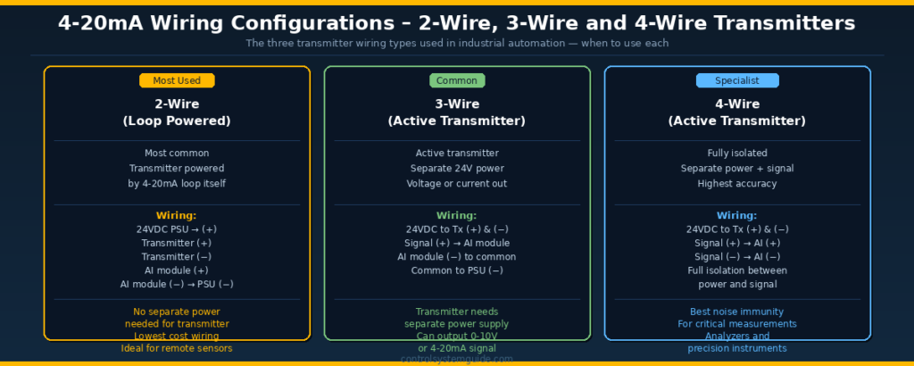
4-20mA Wiring Configurations
[UPLOAD IMAGE HERE: 4-20ma-signal-wiring.png — Alt text: 4-20mA wiring configurations 2-wire 3-wire 4-wire transmitter explained]
2-Wire (Loop Powered) — Most Common
The transmitter is powered directly by the 4-20mA loop itself. Only 2 wires are needed — the same pair carries both the 24VDC power to the transmitter and the 4-20mA signal back to the PLC.
Wiring sequence:
| Connection Point | Wire | Description |
|---|---|---|
| 24VDC PSU (+) | Red (+) | Positive supply from panel PSU |
| Transmitter (+) | Red (+) | Loop power into transmitter |
| Transmitter (−) | Black (−) | Signal output from transmitter |
| AI module (+) | Black (−) | Signal into PLC analog input |
| AI module (−) | To PSU (−) | Loop return to power supply negative |
When to use: Standard process transmitters — pressure, temperature, flow, level. The vast majority of industrial transmitters are 2-wire loop-powered.
3-Wire (Active Transmitter)
The transmitter has its own 24VDC power supply separate from the signal output. Three wires are required — power (+), power (−), and signal output.
When to use: Sensors that output 0-10V or sensors requiring more power than a 2-wire loop can provide. Common with ultrasonic sensors and some optical sensors.
4-Wire (Fully Isolated)
Complete electrical isolation between the power supply and signal circuit. Four wires — two for power, two for signal. Used for analyzers and precision instruments where isolation is required to eliminate ground loops.
When to use: Analytical instruments (pH, conductivity), precision load cells, and applications where ground loops cause measurement errors.
How to Scale 4-20mA in PLC Programs
The PLC analog input module converts the 4-20mA current to a raw digital integer. This raw value must be scaled to engineering units (°C, bar, m³/h) before it can be used in control logic.
Raw Value Ranges
| PLC Platform | At 4mA (0%) | At 12mA (50%) | At 20mA (100%) |
|---|---|---|---|
| Siemens S7-1200/1500 | 5,530 | 16,589 | 27,648 |
| Allen-Bradley (Studio 5000) | 3,277 (or 0 if scaled) | 16,384 | 32,767 |
| Mitsubishi iQ-R | 0 | 8,000 | 16,000 |
| Omron NX/NJ | 0 | 10,000 | 20,000 |
Scaling in Siemens TIA Portal
Use the NORM_X and SCALE_X function blocks:
| Block | Input | Output | Example |
|---|---|---|---|
| NORM_X | Raw value (5530–27648) | Normalized 0.0–1.0 | %IW64 → 0.0 to 1.0 |
| SCALE_X | Normalized 0.0–1.0 | Engineering units | 0.0–1.0 → 0.0–100.0°C |
Example — Scale %IW64 to 0-100°C temperature:
- NORM_X: MIN = 5530, MAX = 27648, VALUE = %IW64 → Output to Tag “Temp_Norm”
- SCALE_X: MIN = 0.0, MAX = 100.0, VALUE = “Temp_Norm” → Output to Tag “Temperature_degC”
Scaling in Allen-Bradley Studio 5000
Studio 5000 can scale automatically in the analog input module properties — set the Input Range to 4-20mA and enter the Engineering Units Low (0.0) and High (100.0) directly. The module outputs the scaled engineering value directly as a REAL tag without requiring additional scaling instructions in the program.
Alternatively use the SCL (Scale) instruction:
- SCL Source: Raw AI tag (0–32767)
- Rate: (100.0 / 32767) × 65536 = 199.0 (for 0-100 range)
- Offset: 0
- Destination: Temperature_degC (REAL tag)
HART Protocol – Digital Communication on 4-20mA
HART (Highway Addressable Remote Transducer) is a digital communication protocol that superimposes a digital signal on top of the standard 4-20mA analog current loop. It allows two-way digital communication between the control system and the field device without any additional wiring.
| Feature | Detail |
|---|---|
| Signal method | FSK (Frequency Shift Keying) at 1200 baud superimposed on 4-20mA |
| Does it affect 4-20mA? | No — HART signal averages to zero, does not disturb analog reading |
| What HART provides | Device configuration, diagnostics, secondary variables, device ID |
| Tool required | HART communicator (handheld) or HART modem with laptop |
| Wiring required | None — uses existing 2-wire 4-20mA loop |
| Typical use | Remote configuration of transmitters, diagnostics without field visit |
💡 HART in Practice: With a HART communicator you can remotely reconfigure a transmitter’s range, read its serial number, check its diagnostic status, and access secondary measurements (e.g. a multivariable transmitter sending both pressure and temperature) — all without disconnecting the 4-20mA signal or visiting the field location.
How to Troubleshoot 4-20mA Signals
The 4-20mA signal is one of the easiest analog signals to troubleshoot because you only need a standard digital multimeter set to DC milliamperes (mA).
| Symptom | Measured Current | Cause | Fix |
|---|---|---|---|
| PLC reading 0 / under-range alarm | 0mA | Wire break, transmitter not powered, transmitter failed | Check wiring continuity, check 24V supply to loop |
| PLC reading maximum / over-range alarm | >20.5mA | Transmitter over-range, short circuit, wrong wiring | Check process value vs transmitter range, check wiring polarity |
| PLC reading wrong value | Correct mA, wrong EU | Incorrect scaling in program or module configuration | Verify NORM_X/SCALE_X parameters or module engineering unit settings |
| PLC reading noisy / fluctuating | Fluctuating mA | Unshielded cable, cable near power wiring, ground loop | Replace with shielded twisted pair, re-route cable, check shield grounding |
| PLC reading fixed value regardless of process | Fixed mA | Transmitter failed in fixed output mode | Replace transmitter |
| Two PLCs reading different values from same transmitter | Split loop | Multiple devices in loop exceeding voltage budget | Use a 4-20mA signal splitter/isolator |
Step-by-Step Measurement with a Multimeter
The HART Communication Foundation recommends measuring loop current at the AI module terminals as the first step in any analog signal fault investigation.Step-by-Step Measurement with a Multimeter
- Set multimeter to DC mA range (20mA or 200mA)
- Break the loop at any convenient point (e.g. at the AI module terminal)
- Connect multimeter in series — red lead to incoming wire, black lead to AI terminal
- Read the mA value — should be between 4.0 and 20.0mA for a healthy signal
- Compare to expected value based on current process condition
💡 Non-Invasive Measurement: A clamp meter with a 4-20mA DC current range can measure the loop current without breaking the circuit. Wrap the wire 10 times through the clamp and divide the reading by 10 for better resolution on small signals.
Common 4-20mA Wiring Mistakes
Mistake 1 — Connecting 4-20mA transmitter to a voltage input
Connecting a 4-20mA transmitter to a 0-10V analog input module will give completely wrong readings. Always verify whether the AI module is configured for current (mA) or voltage (V) input — most modules have both options selectable by jumper or software.
Mistake 2 — Reversed polarity wiring
Connecting the transmitter positive to the AI module negative and vice versa. The transmitter will not power up correctly and may read 0mA or show erratic behavior. Always follow the loop wiring: PSU(+) → Transmitter(+) → Transmitter(−) → AI(+) → AI(−) → PSU(−).
Mistake 3 — Shield grounded at both ends
Grounding the cable shield at both the field instrument and the panel creates a ground loop — a small current flows through the shield, inducing noise into the signal. Always ground the shield at one end only — at the control panel end.
Mistake 4 — Too many devices in series causing voltage budget overrun
Each device in the 4-20mA loop has a voltage drop (burden resistance × 20mA). If the total voltage drops exceed the supply voltage minus transmitter minimum voltage, the loop will not function correctly. Use signal splitters/isolators when connecting multiple devices to the same loop.
Mistake 5 — Incorrect scaling parameters
Entering the wrong MIN or MAX values in NORM_X/SCALE_X (Siemens) or in the module engineering units (Allen-Bradley). Always verify: does the PLC read 4mA = 0% and 20mA = 100% before going live? Use a signal simulator or force a known mA value for verification.
Frequently Asked Questions – 4-20mA Signal
What is a 4-20mA signal?
A 4-20mA signal is an analog current loop standard used to transmit sensor measurements in industrial automation. The current varies linearly between 4 milliamperes (representing 0% of the measurement range) and 20 milliamperes (representing 100%). It is the most widely used analog signal standard in process industries worldwide because of its noise immunity, long-distance capability, and built-in wire break detection.
Why does the 4-20mA signal start at 4mA instead of 0mA?
Starting at 4mA instead of 0mA creates what is called a live zero. In a healthy 4-20mA loop 0mA is physically impossible — the minimum measurable value produces 4mA. If the signal ever drops to 0mA it can only mean the wire is broken, the transmitter has lost power, or the transmitter has failed. This allows the control system to immediately detect a fault condition rather than confusing a wire break with a zero measurement.
What is the difference between 4-20mA and 0-10V signals?
The 4-20mA signal uses current which remains constant throughout a series circuit regardless of cable resistance — making it suitable for cable runs over 1000 meters. The 0-10V signal uses voltage which drops across cable resistance, causing measurement errors over long distances. The 4-20mA signal also provides wire break detection and has much better immunity to electrical noise from motors and drives. The 0-10V signal is simpler and faster but only suitable for short cable runs in low-noise environments.
How do I wire a 4-20mA transmitter to a PLC?
For a 2-wire loop-powered transmitter connect the positive terminal of your 24VDC power supply to the positive terminal of the transmitter. Connect the negative terminal of the transmitter to the positive terminal of the PLC analog input module. Connect the negative terminal of the AI module back to the negative terminal of the power supply. This creates a complete series loop carrying both power and signal on two wires.
How do I scale 4-20mA to engineering units in Siemens TIA Portal?
Use two function blocks in sequence. First use NORM_X with MIN set to 5530 and MAX set to 27648 — this normalizes the raw analog input value to a real number between 0.0 and 1.0. Then use SCALE_X with your engineering unit range — for example MIN 0.0 and MAX 100.0 for a 0 to 100 degree Celsius temperature transmitter. The output of SCALE_X gives you the measurement in engineering units directly usable in your program.
What does 0mA mean on a 4-20mA loop?
A reading of 0mA on a 4-20mA loop always indicates a fault condition — never a valid process measurement. The most common causes are a broken signal wire, the transmitter losing its 24VDC supply power, or a failed transmitter. The control system should generate an immediate fault alarm when 0mA is detected. Investigate by measuring the 24V supply at the transmitter terminals and checking cable continuity.
What is HART and how does it work with 4-20mA?
HART (Highway Addressable Remote Transducer) is a digital communication protocol that superimposes a low-level digital signal on top of the existing 4-20mA analog current loop. It uses frequency shift keying at 1200 baud and averages to zero so it does not disturb the analog measurement. HART allows two-way digital communication for remote device configuration, diagnostics, and access to secondary measurements — all without any additional wiring beyond the existing 4-20mA loop.
Can I connect multiple devices to one 4-20mA loop?
You can connect multiple receiving devices such as a PLC analog input, a chart recorder, and an alarm unit in series on one 4-20mA loop — but each device adds a voltage burden (typically 250 ohms multiplied by 20mA = 5 volts per device). The total voltage burden of all devices must not exceed the available loop voltage (supply voltage minus transmitter minimum operating voltage, typically 12V). If too many devices are needed use a 4-20mA signal splitter or isolator to create independent loops from one transmitter output.
Conclusion
The 4-20mA signal has remained the dominant standard in industrial instrumentation for over 60 years because it solves real engineering problems better than any alternative — noise immunity, long-distance transmission, live zero fault detection, and two-wire simplicity.
Key points to remember:
- 4mA = 0% (minimum measurement), 20mA = 100% (maximum measurement)
- 0mA always means FAULT — wire break, no power, or failed transmitter
- 2-wire loop-powered is the most common wiring — same 2 wires carry power and signal
- Scale raw values using NORM_X + SCALE_X in Siemens, or module EU settings in Allen-Bradley
- Always use shielded twisted-pair cable — shield grounded at panel end only
- HART protocol rides on the 4-20mA loop for digital diagnostics at no extra wiring cost
Related Guides:
- PLC Inputs and Outputs – DI, DO, AI, AO Complete Guide
- PLC Troubleshooting Guide – Step-by-Step Fault Finding
- PLC IO List – Free Excel Template + 7 Real Examples
- What Is a PLC? Complete Beginner’s Guide
Automation engineer based in Asia, with hands-on experience in PLC programming, SCADA, and industrial control systems across oil and gas, power, food and beverage, and water industries. Writes about PLC fundamentals, ladder logic, vendor-specific instruction sets for Siemens, Allen-Bradley, and other major platforms, and industrial communication protocols.