Last Updated: April 2026 | Written for automation engineers and beginners learning industrial PLC wiring.
PLC wiring is the physical foundation of every industrial automation system. No matter how well a PLC program is written, if the field devices are wired incorrectly the system will not work. This complete PLC wiring guide covers every signal type — digital inputs, digital outputs, analog inputs, analog outputs — with clear wiring rules, sensor matching guidance, and common mistakes to avoid.
In this complete PLC wiring guide you will learn:
- The fundamental rules every PLC wiring circuit must follow
- How to wire digital inputs (DI) — push buttons, sensors, limit switches
- The critical difference between sourcing (PNP) and sinking (NPN) — explained clearly
- How to wire digital outputs (DO) — relay, transistor and triac types
- How to wire analog inputs (AI) — 4-20mA 2-wire and 3-wire configurations
- How to wire analog outputs (AO) — control valves and VFD drives
- Essential cable selection, earthing and shielding rules
- The most common PLC wiring mistakes and how to avoid them
For a complete understanding of PLC IO signal types before wiring, read: PLC Inputs and Outputs – DI, DO, AI, AO Complete Guide
PLC Wiring Fundamentals – Rules Every Circuit Must Follow
Before touching any wire, understand the three elements every PLC wiring circuit must have:
| Element | Description | Example |
|---|---|---|
| Current Source | Power supply providing voltage — 24VDC or 120/240VAC | 24VDC panel power supply |
| Load | The device consuming current in the circuit | Push button, sensor, contactor coil |
| Return Path | Complete circuit path back to power supply negative/neutral | 0V rail back to PSU negative |
💡 Golden Rule: Every PLC wiring circuit must form a complete loop — current must flow from the positive supply terminal, through the load, and back to the negative supply terminal. If this loop is broken at any point the circuit will not work. Approximately half of all PLC wiring faults are caused by incomplete circuit loops.
Standard PLC Wiring Voltage
| Signal Type | Typical Voltage | Description |
|---|---|---|
| Digital inputs (DC) | 24VDC | Industry standard — safe low voltage |
| Digital inputs (AC legacy) | 120VAC or 240VAC | Older installations — being phased out |
| Digital outputs (transistor) | 24VDC | Modern — fast switching, long life |
| Digital outputs (relay) | 24VDC or 230VAC | Flexible — handles AC and DC loads |
| Analog signals | 4-20mA or 0-10V | Process signals — shielded cable required |
| PLC CPU power supply | 24VDC (S7-1200) or 120/240VAC | Depends on CPU model variant |
PLC Wiring – Digital Input (DI) Wiring
Digital inputs are the most common wiring task in PLC panel building. A digital input receives an ON/OFF signal from a field device — push button, limit switch, proximity sensor, or photoelectric sensor — and sends it to the PLC CPU for processing.
Basic Digital Input Wiring — Push Button
The simplest digital input is a push button. Here is the wiring sequence for a 24VDC digital input:
| Connection Point | Wire | Description |
|---|---|---|
| 24VDC PSU (+) | Red (+24V) | Positive supply to button terminal |
| Push button terminal 1 | Red (+24V) | Supply into button |
| Push button terminal 2 | Signal wire | Output from button to DI terminal |
| PLC DI terminal (e.g. I0.0) | Signal wire | Input channel terminal |
| PLC COM / M terminal | Blue (0V) | Return path to PSU negative |
| 24VDC PSU (−) | Blue (0V) | Negative/common return |
NO vs NC Contact Wiring
| Contact Type | Normal State | When Activated | PLC Bit | Use For |
|---|---|---|---|---|
| NO (Normally Open) | Circuit open — 0V at input | Circuit closed — 24V at input | 0 → 1 | Start buttons, sensors, general inputs |
| NC (Normally Closed) | Circuit closed — 24V at input | Circuit open — 0V at input | 1 → 0 | Stop buttons, E-stop, safety devices |
⚠️ Safety Rule: Emergency stop buttons and safety devices must ALWAYS be wired as Normally Closed (NC) contacts. If the cable breaks or the connection is lost, an NC contact opens — the PLC sees the input go FALSE and can stop the machine safely. An NO emergency stop does nothing if the cable breaks — the machine keeps running with no way to stop it.
PLC Wiring – Sourcing vs Sinking (PNP vs NPN)
Sourcing vs sinking is the most confusing topic in PLC wiring for beginners — yet it is fundamental to correctly connecting sensors to PLC inputs. Getting this wrong means the input simply never activates regardless of sensor state.
What Is Sourcing (PNP)?
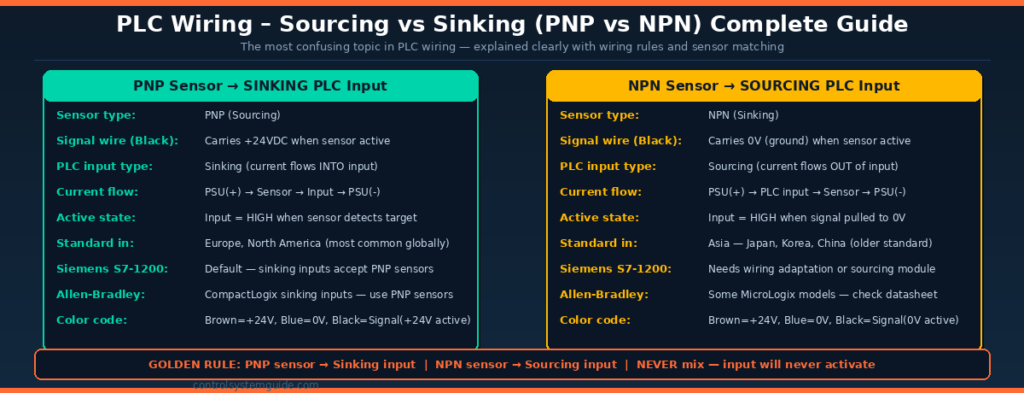
A PNP (sourcing) sensor switches the positive supply (+24V) to its output signal wire when it detects a target. The signal wire carries +24VDC in the active state. This is called “sourcing” because the sensor provides (sources) current to the PLC input.
A sinking PLC input accepts current flowing into it from a PNP sensor. The current path is: PSU(+) → Sensor → PLC Input terminal → PLC COM terminal → PSU(−).
What Is Sinking (NPN)?
An NPN (sinking) sensor switches its output signal wire to 0V (ground) when it detects a target. The signal wire carries 0VDC in the active state. This is called “sinking” because the sensor accepts (sinks) current from the PLC input.
A sourcing PLC input provides current that flows out through the input terminal, through the NPN sensor, and back to ground.
Sensor Matching Rule
| Sensor Type | PLC Input Type Required | Signal Wire Active State | Standard Region |
|---|---|---|---|
| PNP (Sourcing) | Sinking input | +24VDC when active | Europe, North America — most common |
| NPN (Sinking) | Sourcing input | 0V (ground) when active | Asia — Japan, Korea, China |
Sensor Color Code (Standard)
| Wire Color | Function | Connection |
|---|---|---|
| Brown | Positive supply | Connect to +24VDC |
| Blue | Negative / common | Connect to 0V |
| Black | Signal output | Connect to PLC DI terminal |
| White | Second output (if present) | Complementary output — use one only |
Siemens S7-1200 Sensor Wiring
The Siemens S7-1200 has sinking digital inputs by default — this means it requires PNP (sourcing) sensors. The wiring is: Brown → +24V, Blue → 0V, Black (signal) → DI terminal. The COM terminal on the S7-1200 connects to 0V.
Allen-Bradley CompactLogix Sensor Wiring
Allen-Bradley CompactLogix digital inputs are also sinking type in most models — requiring PNP (sourcing) sensors. Always verify by checking the module datasheet for “Sinking” or “Sourcing” designation before wiring.
PLC Wiring – Digital Output (DO) Wiring
Digital outputs send ON/OFF control signals from the PLC to field actuators — motor contactors, solenoid valves, indicator lamps, and alarm horns. The wiring method depends on the output module type.
Relay Output Wiring
Relay outputs use mechanical contacts — when the PLC activates the output, the relay coil energizes and closes the relay contact, completing the load circuit. Relay outputs are isolated and can switch both AC and DC loads.
| Terminal | Connection | Notes |
|---|---|---|
| PLC DO terminal (e.g. Q0.0) | One side of relay contact | This is the switched terminal |
| Load supply + | Other side of relay contact | Can be 24VDC or 230VAC |
| Load device (coil/lamp) | Between relay contact and return | Contactor coil, solenoid, lamp |
| Load supply −/N | Return from load back to PSU | Complete the circuit |
Transistor (Solid State) Output Wiring
Transistor outputs switch DC loads only. They are faster and more reliable than relay outputs but require correct polarity wiring.
| Terminal | Connection | Notes |
|---|---|---|
| PLC DO terminal (e.g. Q0.0) | Load device positive terminal | Output switches +24VDC to load |
| Load device negative terminal | 0V return to PSU negative | Complete circuit through load |
| PLC L+ terminal | +24VDC supply to output module | Powers the output transistors |
| PLC M terminal | 0V return | Module common negative |
Output Type Selection Guide
| Load Type | Recommended Output | Reason |
|---|---|---|
| Motor contactors (24VDC coil) | Relay or Transistor | Both work — transistor for fast cycling |
| Motor contactors (230VAC coil) | Relay only | Transistor outputs are DC only |
| Solenoid valves (24VDC) | Transistor preferred | Faster, longer life, no arc |
| Indicator lamps (24VDC) | Transistor | Clean switching, long life |
| High-current loads (>2A) | Relay via intermediate relay | Transistor module ratings often limited to 0.5-2A |
| AC loads (solenoids, heaters) | Relay or Triac | DC transistor outputs cannot switch AC |
PLC Wiring – Analog Input (AI) Wiring
Analog inputs receive continuously variable signals from field transmitters — temperature, pressure, flow, and level. The most common analog signal is 4-20mA. Correct wiring is critical for accurate readings.
2-Wire Loop-Powered Transmitter (Most Common)
In a 2-wire configuration the transmitter is powered by the 4-20mA loop itself — no separate power cable needed. This is the standard for most process transmitters.
| Connection Sequence | Wire | Description |
|---|---|---|
| 24VDC PSU (+) | Red (+24V) | Loop power supply positive |
| Transmitter (+) terminal | Red (+24V) | Power into transmitter |
| Transmitter (−) terminal | Signal wire | 4-20mA signal out of transmitter |
| PLC AI (+) terminal | Signal wire | Signal into AI module positive |
| PLC AI (−) terminal | Blue (0V) | AI module negative return |
| 24VDC PSU (−) | Blue (0V) | Loop return to PSU negative |
3-Wire Active Transmitter
3-wire transmitters have a separate power supply connection and an independent signal output. Used for sensors that output 0-10V or sensors requiring more power than a 2-wire loop provides.
| Wire Color | Connection | Description |
|---|---|---|
| Brown (+24V) | +24VDC supply | Transmitter power supply positive |
| Blue (0V) | 0V common | Transmitter power supply negative |
| Black (signal) | PLC AI terminal | 4-20mA or 0-10V signal output |
Analog Input Wiring Rules
- Always use shielded twisted-pair cable for analog signals
- Connect shield to earth at the panel end only — never at both ends
- Route analog cables in separate cable trays from power cables
- Keep analog cable runs as short as practical
- Verify AI module is configured for current (mA) or voltage (V) — matches your transmitter
- Always verify: 4mA = 0% and 20mA = 100% before going live
For the complete 4-20mA signal guide: 4-20mA Signal Explained – Complete Industrial Guide
PLC Wiring – Analog Output (AO) Wiring
Analog outputs send continuously variable signals from the PLC to control devices — control valves, variable frequency drives, and dosing pumps. The most common AO signal is 4-20mA.
| Device | Signal | Wiring | Control Effect |
|---|---|---|---|
| Pneumatic control valve | 4-20mA → I/P positioner | AO(+) → positioner(+), AO(−) → positioner(−) | 4mA=closed, 20mA=fully open |
| Variable Frequency Drive (VFD) | 4-20mA or 0-10V | AO terminal → VFD analog input terminal | 4mA=0Hz, 20mA=max speed |
| Dosing pump | 4-20mA | Same as control valve — 2-wire connection | Controls pump stroke rate |
| Motorized damper | 0-10V | AO(+) → actuator(+), AO(−) → actuator(−) | 0V=closed, 10V=fully open |
PLC Wiring – Cable Selection Guide
| Signal Type | Cable Type | Minimum Cross-Section | Shield Required? |
|---|---|---|---|
| Digital inputs (24VDC) | Standard PVC multi-core | 0.75mm² (18 AWG) | ❌ No — not required |
| Digital outputs (24VDC low current) | Standard PVC multi-core | 0.75mm² (18 AWG) | ❌ No |
| Digital outputs (high current >2A) | Standard PVC — larger cross-section | 1.5mm² (16 AWG) minimum | ❌ No |
| Analog 4-20mA | Shielded twisted pair (STP) | 0.5mm² (20 AWG) | ✅ Yes — mandatory |
| Analog 0-10V | Shielded twisted pair (STP) | 0.5mm² (20 AWG) | ✅ Yes — mandatory |
| Thermocouple extension cable | Thermocouple-grade compensating cable | Match TC type (J, K, T) | ✅ Yes — mandatory |
| PROFINET / EtherNet/IP | Industrial Ethernet Cat6 or Cat6A | AWG 22-26 (standard Ethernet) | ✅ Yes — use STP Ethernet |
PLC Wiring – Earthing and Shielding Rules
Incorrect earthing is one of the most common causes of electrical noise, erratic readings, and mysterious faults in PLC panels. Follow these rules on every installation:
| Rule | Detail | Why |
|---|---|---|
| Earth PLC CPU chassis | Connect CPU PE terminal to panel earth bar | Safety and noise immunity |
| Earth power supply chassis | Connect PSU earth terminal to panel earth bar | Safety ground reference |
| Shield analog cables at panel end only | Connect shield drain wire to earth at panel — leave other end floating | Prevents ground loops |
| Never connect shield at both ends | Connecting shield at both ends creates a ground loop — induces noise | Eliminates noise pickup |
| Separate analog and power cables | Route in separate cable trays — minimum 100mm separation | Prevents EMI interference |
| Use star earthing topology | All earth connections return to single panel earth bar — no daisy chains | Consistent earth reference |
| Earth bar to building earth | Panel earth bar connected to building structural earth via green/yellow cable | Safety and noise reference |
Common PLC Wiring Mistakes
Mistake 1 — Wrong sensor type for PLC input (NPN/PNP mismatch)
Connecting an NPN sensor to a sinking PLC input (or PNP to sourcing) means the input never activates regardless of sensor state. Always check the PLC module datasheet for “Sinking” or “Sourcing” designation and match it to the correct sensor type. PNP → Sinking input. NPN → Sourcing input.
Mistake 2 — Emergency stop wired as Normally Open
An NO emergency stop does nothing if the cable breaks. Always wire E-stops and safety devices as Normally Closed — if the wire breaks the PLC sees the input go FALSE and stops the machine. This is a fundamental safety requirement under IEC 60204-1.
Mistake 3 — Analog cable shield connected at both ends
Grounding the analog cable shield at both the field instrument and the panel creates a ground loop — a small current flows through the shield, inducing electrical noise directly into the signal. Always connect shield at the panel end only and leave the field end floating.
Mistake 4 — Analog cables routed alongside power cables
Running 4-20mA or 0-10V cables in the same cable tray as 230VAC motor cables or VFD output cables causes severe electromagnetic interference. Maintain at least 100mm physical separation — ideally use separate cable trays for analog and power wiring.
Mistake 5 — Exceeding output module current rating
Each transistor output channel has a maximum current rating — typically 0.5A to 2A. Connecting a large contactor coil or multiple loads directly to one output channel can exceed this rating, causing the module to overheat or fail. Use intermediate relays for loads exceeding 0.5A per channel.
Mistake 6 — No suppression on inductive loads
Relay coils, contactor coils, and solenoid valves are inductive loads — when switched off they generate a voltage spike that can damage transistor output modules. Always fit a freewheeling diode (for DC loads) or RC snubber (for AC loads) across each inductive load to suppress voltage spikes.
Mistake 7 — Wrong analog module configuration
Most PLC analog input modules support both 4-20mA and 0-10V inputs — selected by jumper or software configuration. Connecting a 4-20mA transmitter to a module configured for 0-10V gives completely wrong readings. Always verify module configuration matches the connected device before commissioning.
PLC Wiring Safety Standards
All PLC panel wiring must comply with applicable electrical safety standards. Key standards include:
| Standard | Scope | Key Requirement |
|---|---|---|
| IEC 60204-1 | Safety of machinery — electrical equipment | E-stop wiring, cable sizing, earthing requirements |
| NFPA 79 | Electrical standard for industrial machinery (USA) | Panel layout, wiring methods, overcurrent protection |
| IEC 61131-2 | PLC equipment requirements | PLC IO voltage standards, immunity requirements |
| IEC 62443 | Industrial cybersecurity | Network segregation, secure communications |
According to the International Electrotechnical Commission (IEC), IEC 60204-1 is the primary standard governing electrical safety in industrial machinery including PLC panel wiring requirements.
Frequently Asked Questions – PLC Wiring
What is sourcing and sinking in PLC wiring?
Sourcing and sinking describe the direction of current flow through a PLC digital input circuit. A sinking PLC input accepts current flowing into the input terminal — it requires a PNP (sourcing) sensor that switches positive voltage to its output. A sourcing PLC input provides current that flows out of the input terminal — it requires an NPN (sinking) sensor that switches ground to its output. The golden rule is: PNP sensor with sinking input, NPN sensor with sourcing input.
What type of sensor should I use with a Siemens S7-1200?
The Siemens S7-1200 has sinking digital inputs by default — this means you must use PNP (sourcing) sensors. Connect the sensor brown wire to +24VDC, blue wire to 0V, and black signal wire to the DI terminal. The S7-1200 COM terminal connects to 0V. This is the standard configuration for most European and North American proximity sensors and photoelectric sensors.
Why must emergency stop buttons be wired as Normally Closed?
Emergency stop buttons must be wired Normally Closed because this creates a fail-safe circuit. When the cable is healthy the input reads TRUE (circuit closed). If the cable breaks or the connector comes loose the input drops to FALSE — the same as pressing the E-stop. The PLC can then stop the machine safely. A Normally Open E-stop would read FALSE when healthy and only go TRUE when pressed — but a broken cable would also read FALSE and the machine would keep running with no protection.
What cable should I use for 4-20mA analog signals?
Always use shielded twisted-pair cable for 4-20mA analog signals. The twisted pair reduces electromagnetic interference pickup and the shield provides additional noise protection. Connect the cable shield to earth ground at the panel (control room) end only — leave the field instrument end of the shield floating and unconnected. Never connect the shield at both ends as this creates a ground loop that induces noise into the signal.
What is the difference between relay and transistor PLC outputs?
Relay outputs use mechanical contacts that can switch both AC and DC loads at various voltages — they are versatile but slower and have a limited lifetime of around one million switching operations. Transistor outputs use solid-state semiconductor switching — they are faster, have no mechanical wear, but only switch DC loads and require correct polarity wiring. Use transistor outputs for high-speed switching and long-life applications. Use relay outputs for AC loads or when load voltage does not match the module supply voltage.
How do I wire a 4-20mA transmitter to a PLC?
For a 2-wire loop-powered transmitter: connect the positive terminal of your 24VDC power supply to the transmitter positive terminal. Connect the transmitter negative terminal to the PLC analog input positive terminal. Connect the PLC analog input negative terminal back to the power supply negative. This creates a complete series loop — the same two wires carry both the 24VDC power to the transmitter and the 4-20mA signal back to the PLC.
Why do I need to fit a diode across a relay coil?
Relay coils and contactor coils are inductive loads. When the PLC switches off the output and the coil de-energizes, the magnetic field collapses and generates a large reverse voltage spike — often hundreds of volts — that can damage the output transistor module. A freewheeling diode connected in reverse polarity across the coil provides a path for this spike current to flow harmlessly, protecting the output module. Always fit suppression on inductive DC loads connected to transistor outputs.
What is the maximum cable length for 4-20mA signals?
The 4-20mA signal can reliably transmit over very long distances — typically 300 to 1000 meters or more depending on cable resistance and the power supply voltage available to the loop. The maximum distance is determined by the total loop resistance — cable resistance plus transmitter burden resistance plus PLC input resistance — which must not exceed the available voltage divided by 20mA. For most 24VDC systems with standard 0.5mm² cable this allows cable runs well over 500 meters without signal degradation.
Conclusion
Correct PLC wiring is just as important as correct PLC programming. A well-written program will not work if sensors are connected to the wrong input type, analog cables are unshielded, or emergency stops are wired as normally open contacts.
Key rules to remember for every PLC wiring job:
- Every circuit needs a complete loop — source, load, and return path
- PNP sensors → Sinking inputs — NPN sensors → Sourcing inputs
- E-stops and safety devices — always wire Normally Closed
- Analog cables — shielded twisted pair, shield grounded at panel end only
- Separate analog cables from power cables by at least 100mm
- Fit diodes or snubbers across all inductive loads on transistor outputs
- Verify module configuration — mA or V — before connecting transmitters
Related Guides:
- PLC Inputs and Outputs – DI, DO, AI, AO Complete Guide
- 4-20mA Signal Explained – Complete Industrial Guide
- PLC Troubleshooting Guide – Step-by-Step Fault Finding
- PLC IO List – Free Excel Template + 7 Real Examples
Automation engineer based in Asia, with hands-on experience in PLC programming, SCADA, and industrial control systems across oil and gas, power, food and beverage, and water industries. Writes about PLC fundamentals, ladder logic, vendor-specific instruction sets for Siemens, Allen-Bradley, and other major platforms, and industrial communication protocols.