Last Updated: May 2026 | A step-by-step guide for beginners learning to read PLC ladder logic programs.
Learning how to read ladder logic is the first practical skill every PLC programmer, electrician, and automation technician needs. Once you can read a rung in your head — left to right, top to bottom — every PLC program in the world becomes accessible to you. This step-by-step guide walks you through reading ladder logic from absolute zero, using real industrial rungs as worked examples.
By the end of this guide you will be able to look at any ladder logic diagram — in Allen-Bradley Studio 5000, Siemens TIA Portal, or any other PLC platform — and understand exactly what it does.
In this how-to-read ladder logic guide you will learn:
- The 5-step method for reading any ladder logic rung
- How to identify rails, rungs, contacts, and coils at a glance
- How to follow virtual current flow through a rung
- How to translate ladder logic into plain English sentences
- How to read parallel branches, series contacts, and seal-ins
- The most common reading mistakes beginners make
Why Reading Ladder Logic Feels Hard at First
Most beginners feel overwhelmed the first time they look at a real ladder logic diagram from a working machine. The symbols look unfamiliar, the layout is dense, and the tag names mean nothing without context. The good news: that feeling disappears completely within an hour of structured practice, because ladder logic is one of the most readable programming languages ever designed.
Reading ladder logic is not like reading a normal programming language. There are no curly braces, no semicolons, no function definitions to chase. It is a visual language. Every rung is a complete sentence, the layout tells you exactly what the program is doing, and you can verify behavior by tracing virtual current with your eye.
If you are completely new to ladder logic, start with the foundational PLC Ladder Logic Tutorial first to understand what the symbols look like. Then return here to learn how to read them.
Ladder Logic Anatomy — Rails and Rungs
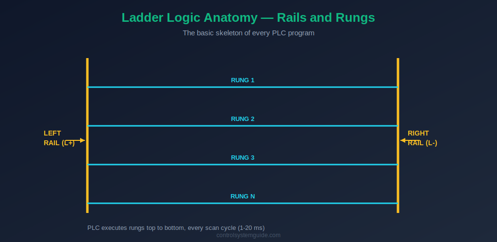
Every ladder logic program has the same skeleton: two vertical lines on the sides called rails, and horizontal lines between them called rungs. The left rail represents the power source (L+), and the right rail represents the return path (L-). Virtual current flows from the left rail, across the rung, to the right rail — but only if the conditions on the rung allow it.
Each rung is one complete piece of logic. The PLC processes rungs one at a time, starting at the top, going down. Rung 1 first, then Rung 2, then Rung 3, and so on. This happens during every scan cycle — typically 1 to 20 milliseconds — repeating continuously while the PLC is running. To learn more about how the PLC executes rungs, read our PLC Scan Cycle Guide.
Understanding this structure is the foundation. Before learning to read individual symbols, train your eye to immediately spot the rails on the sides and number the rungs in your head from top to bottom.
How to Read Ladder Logic — The 5-Step Method
This is the method I teach every junior engineer on their first day with a PLC. Apply these five steps in order to every rung you encounter, and you will be able to read any ladder logic program — in any vendor’s software.
Step 1 — Find the Rails, Count the Rungs
Look at the diagram. Find the two vertical lines on the left and right side — those are the rails. Look at how many horizontal lines connect them. Each horizontal line is one rung. Number them mentally: Rung 1 at the top, then Rung 2, Rung 3, and so on down the page.
Why this matters: the PLC reads rungs in exactly this order during every scan. Outputs from earlier rungs can be used as inputs in later rungs. If you read the rungs out of order in your head, you will misunderstand the logic.
Step 2 — Read the Inputs on the Left Side
On every rung, the left side contains input conditions called contacts. Two contact symbols cover 95% of ladder logic:
- Normally Open contact (NO):
--| |--or Allen-Bradley XIC — passes current when the bit is ON - Normally Closed contact (NC):
--|/|--or Allen-Bradley XIO — passes current when the bit is OFF
Above each contact you will see a tag name like Start_PB, Stop_PB, or an address like I0.0. That tag identifies which physical input the contact is watching. For each contact, ask yourself: is this contact TRUE or FALSE right now?
For the full set of contact symbols including edge detection, see our Ladder Logic Symbols Guide.
Step 3 — Follow the Virtual Current Left to Right
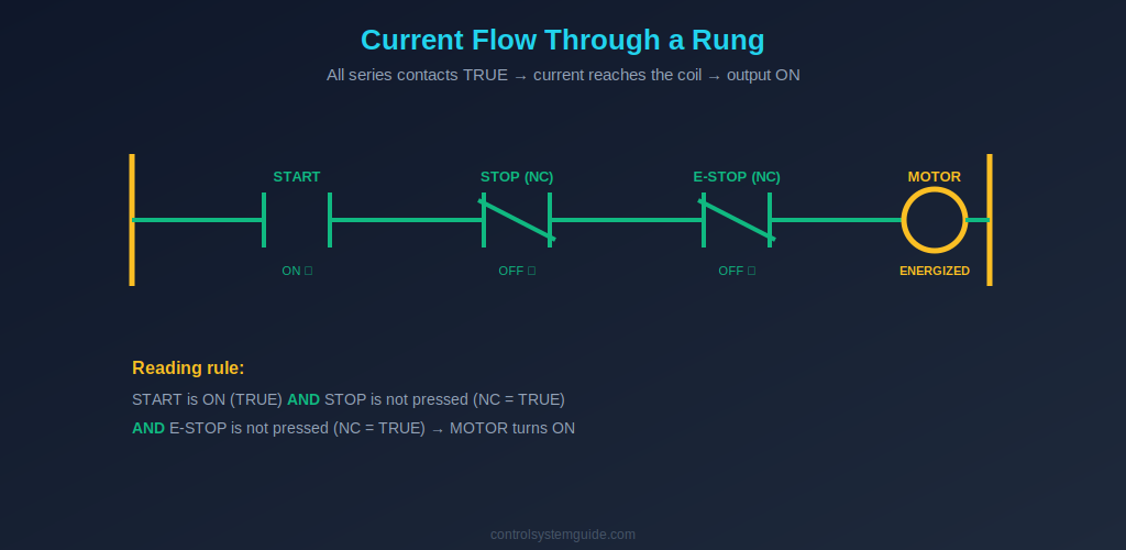
Imagine virtual current flowing from the left rail toward the right side of the rung. Current can only flow through contacts that are TRUE. If you hit a FALSE contact in series, the current stops there — the rung is broken and no output happens.
Series rule (AND logic): If contacts are next to each other on the same horizontal line, ALL of them must be TRUE for current to reach the right side. That is AND logic.
Parallel rule (OR logic): If contacts are stacked above each other in a branch, only ONE of them needs to be TRUE for current to reach the right side. That is OR logic.
Combining series and parallel branches is how every ladder logic program is built — even the most complex ones.
Step 4 — Identify the Output on the Right Side
The output appears on the right side of the rung — usually a coil symbol --( )-- with a tag name like Motor_Run, Lamp_On, or Q0.0. The coil takes the action.
The rule is simple: if the virtual current reached the coil, the output is ON. If the current was blocked anywhere on the left side, the output is OFF. There is no in-between for digital outputs.
You may also see special coil types:
- Set / Latch coil
--(S)--— turns the output ON and keeps it ON, even after the rung goes FALSE - Reset / Unlatch coil
--(R)--— clears a latched output
Step 5 — Move to the Next Rung
Once Rung 1 makes sense, move down to Rung 2. Repeat the same five steps. Keep going until you have read every rung.
Watch for tags that appear as outputs in one rung and as inputs in a later rung. This is how the PLC chains logic together — Rung 1’s output becomes Rung 5’s input, and so on. These chains are how complex behavior is built from simple individual rules.
Translate Ladder Logic into Plain English Sentences
The fastest way to learn how to read ladder logic is to translate every rung you see into a plain English sentence in your head. This forces you to identify each element and understand the logical relationship.
The pattern is always the same: “If [input conditions], then [output action].”
Worked Example 1 — Motor Start/Stop
Imagine a rung with a START NO contact in parallel with a MOTOR seal-in contact, followed by a STOP NC contact, followed by an E_STOP NC contact, driving a MOTOR output coil.
Plain English translation: “If START is pressed OR the MOTOR is already running, AND STOP is not pressed, AND E-STOP is not pressed — then turn the MOTOR ON.”
This single rung is the most common ladder logic pattern in industrial automation. Once you can translate it like this, you have mastered the most important pattern in ladder logic.
Worked Example 2 — Tank Fill Control
Imagine a rung with a LOW_LEVEL NO contact, in series with a HIGH_LEVEL NC contact, in series with an AUTO_MODE NO contact, driving a FILL_VALVE output coil.
Plain English translation: “If the tank level is low AND the tank level is not high AND the system is in auto mode — then open the FILL VALVE.”
Worked Example 3 — Conveyor with Jam Detection
Imagine a rung with a PRODUCT_SENSOR NO contact in parallel with a CONVEYOR seal-in contact, in series with a END_LIMIT NC contact, in series with a JAM_SENSOR NC contact, driving a CONVEYOR output coil.
Plain English translation: “If a product is detected OR the conveyor is already running, AND the end limit is not reached, AND there is no jam — then run the CONVEYOR.”
💡 Reading Tip: Practice translating rungs out loud to a colleague or even to yourself. The act of speaking the logic forces your brain to commit to an interpretation — and any mistake becomes immediately obvious. This is the single fastest way to become fluent in reading ladder logic.
How to Read Common Ladder Logic Patterns
Real PLC programs are built from a small set of recurring patterns. Learn to recognize these patterns instantly and your reading speed will jump dramatically.
The Seal-In Pattern
This is the most common pattern in any ladder logic program. It looks like this: a momentary input (like a Start push button) is in parallel with an auxiliary contact of the output coil itself. When the button is pressed, the output energizes — and the auxiliary contact closes in parallel, keeping the rung TRUE even after the button is released.
How to recognize it: Look for an output tag that also appears as a contact in parallel with the start input on the same rung. That is a seal-in.
The Interlock Pattern
An interlock uses a NC contact of one output as a condition for another output. For example, MOTOR_A NC contact in the rung that drives MOTOR_B — meaning Motor B cannot run while Motor A is running.
How to recognize it: Look for NC contacts that reference other output tags. These are interlocks preventing two outputs from being ON at the same time.
The Permissive Pattern
A permissive is a series chain of NO contacts that must all be TRUE before an action is allowed. For example: DOOR_CLOSED + GUARD_LOCKED + OIL_PRESSURE_OK + AUTO_MODE — all in series before MOTOR_START is allowed.
How to recognize it: Look for long series chains of NO contacts. These are permissive conditions — typically safety, position, or mode checks that must all be satisfied.
The Latch / Unlatch Pattern
Two separate rungs work together. The first rung uses an OTL (Set) coil to latch a bit ON when a condition is met. The second rung uses an OTU (Reset) coil to clear that same bit when a different condition is met. The bit stays ON between Set and Reset, regardless of what the input conditions do.
How to recognize it: Look for the same tag appearing on a Set coil in one rung and a Reset coil in another rung. That is a latch / unlatch pair.
Reading Ladder Logic in Siemens vs Allen-Bradley
The logic is identical across both platforms, but the visual and naming conventions differ. Knowing these differences saves confusion when switching between vendors.
| Element | Allen-Bradley Studio 5000 | Siemens TIA Portal |
|---|---|---|
| Normally Open contact | XIC (Examine If Closed) | –| |– (graphical) |
| Normally Closed contact | XIO (Examine If Open) | –|/|– (graphical) |
| Output coil | OTE (Output Energize) | –( )– (graphical) |
| Addressing style | Tag-based (Start_PB) | Address-based (%I0.0) |
| Timer location | Inside ladder rung directly | Requires Instance Data Block |
The five-step reading method works identically for both platforms. The differences are cosmetic — the underlying logic flows the same way.
Common Mistakes When Reading Ladder Logic
1. Confusing XIC with a physical Normally Open contact. XIC is the name of an instruction that examines if a bit is currently TRUE — it does not refer to the physical position of a relay contact in the field. A stop button wired Normally Closed in hardware still uses an XIC contact in the program, because the input is TRUE (ON) when the button is not pressed.
2. Reading rungs out of order. The PLC always executes top to bottom. If Rung 2 uses an output from Rung 1, that output reflects what Rung 1 just set in this scan. Beginners sometimes assume rungs run in parallel — they do not.
3. Ignoring parallel branches. Newcomers often only read the main horizontal line and miss the parallel branches that contain seal-ins or alternative input paths. Always look above and below the main line for branches.
4. Misreading NC contacts. A NC contact passes current when the bit is OFF. Beginners sometimes read it as “always TRUE” because the line looks closed. Always check whether the underlying bit is ON or OFF.
5. Skipping the tag names. The tag name above each contact is the key to understanding what the rung does. A rung with random addresses like I0.0, I0.1, Q0.0 is unreadable; a rung with descriptive tags like Start_PB, Stop_PB, Motor_Run reads like English. Always read the tag, not just the symbol.
Practice Tips for Reading Ladder Logic
Reading ladder logic is a skill, and like all skills it improves with deliberate practice. Here are the methods I recommend to engineers building this skill:
- Read out loud: Translate every rung into a spoken English sentence. Forces interpretation, catches mistakes immediately.
- Practice in a simulator: Free tools like CODESYS or LogixPro let you watch real-time current flow through rungs as inputs change. Best learning environment for beginners. See our guide to PLC software for beginners.
- Read more than you write: In the first three months, spend more time reading other engineers’ programs than writing your own. Pattern recognition matters more than syntax memorization.
- Study small programs in full: A 10-rung motor control program read end-to-end teaches more than 100 random rungs out of context.
- Compare Siemens and Allen-Bradley side by side: Read the same logic in both notations. The mapping between them sticks faster when seen together.
Frequently Asked Questions — Reading Ladder Logic
Is ladder logic easy to read?
Yes, ladder logic is considered the easiest PLC programming language to read, especially for people with an electrical background. The symbols look like familiar electrical relay symbols, and the logic flows left to right and top to bottom — like reading English. Most beginners can read basic motor control rungs within their first hour of learning.
How do I read a ladder logic rung?
Apply the 5-step method: (1) find the rails and number the rungs top to bottom; (2) identify the input contacts on the left side and their tag names; (3) follow virtual current left to right — all series contacts must be TRUE for current to pass; (4) identify the output coil on the right side; (5) move to the next rung. With practice, this takes about 5 seconds per rung.
What does –| |– mean in ladder logic?
The --| |-- symbol is a Normally Open (NO) contact in ladder logic — equivalent to the Allen-Bradley XIC instruction. It passes virtual current (evaluates TRUE) when the referenced bit or input is ON. When the bit is OFF, the contact blocks the rung and no current flows through it.
What does –|/|– mean in ladder logic?
The --|/|-- symbol with the diagonal slash is a Normally Closed (NC) contact in ladder logic — equivalent to the Allen-Bradley XIO instruction. It passes virtual current (evaluates TRUE) when the referenced bit is OFF, and blocks current when the bit is ON. It is the logical inverse of the NO contact.
How do I read parallel branches in ladder logic?
Parallel branches represent OR logic. If two contacts are stacked above each other in a branch, only one of them needs to be TRUE for current to pass through the parallel section. The most common parallel branch is the seal-in pattern, where the output’s own auxiliary contact is placed in parallel with the start input to keep the output energized after the momentary start signal goes away.
How long does it take to learn how to read ladder logic?
Most beginners can read basic motor start/stop rungs within their first hour of structured learning. Reading more complex programs with timers, counters, latching, and sequential logic typically takes 2-4 weeks of regular practice. Becoming truly fluent — reading a 200-rung industrial program at speed and understanding the full machine behavior — takes 3-6 months of working with real systems.
Can I read ladder logic without learning PLC programming?
Yes. Reading ladder logic is a separate skill from writing it. Electricians, maintenance technicians, and field engineers regularly read existing PLC programs to troubleshoot machines without writing new code. The 5-step reading method works whether or not you have ever written a ladder logic program yourself.
Conclusion
Learning how to read ladder logic is one of the highest-leverage skills in industrial automation. Once you can apply the 5-step method to any rung — find the rails, read the inputs, follow the current, identify the output, move to the next rung — every PLC program in the world becomes accessible to you.
Key takeaways for reading ladder logic:
- Read left to right, top to bottom — exactly like English
- Series contacts = AND, parallel branches = OR — the two basic logic patterns
- NO contact is TRUE when ON; NC contact is TRUE when OFF — the core rule
- Translate every rung into an English sentence — the fastest training method
- Practice in a simulator with live current visualization — fastest skill acceleration
Once you are comfortable reading basic rungs, dive into our PLC Ladder Logic Tutorial with 7 worked industrial examples. Each example shows a complete program with multiple rungs that you can practice reading using the 5-step method.
For complete coverage of the symbols you will encounter, bookmark our Ladder Logic Symbols Reference. The international standard that defines all PLC programming notation is IEC 61131-3.
Related Guides:
- PLC Ladder Logic Tutorial – Symbols, Examples & How to Read
- Ladder Logic Symbols – Complete Reference Guide
- PLC Timer Explained — TON, TOF, RTO, TP
- PLC Counter Explained — CTU, CTD, CTUD
- PLC Scan Cycle Explained
- PLC Inputs and Outputs — DI, DO, AI, AO Explained
Automation engineer based in Asia, with hands-on experience in PLC programming, SCADA, and industrial control systems across oil and gas, power, food and beverage, and water industries. Writes about PLC fundamentals, ladder logic, vendor-specific instruction sets for Siemens, Allen-Bradley, and other major platforms, and industrial communication protocols.