Last Updated: May 2026 | 12 complete Allen-Bradley ladder logic examples in Studio 5000 with XIC, XIO, OTE, OTL, OTU, TON, and CTU instructions.
This guide is a complete library of Allen-Bradley ladder logic examples written in Studio 5000 / RSLogix 5000 conventions. Every example uses Allen-Bradley’s instruction set — XIC, XIO, OTE, OTL, OTU, TON, TOF, CTU, RES, MOV, EQU — with tag-based addressing as found in real ControlLogix, CompactLogix, and MicroLogix programs.
The examples are written so you can drop them directly into your own Studio 5000 routine. Each example includes the tag list with correct data types (BOOL, TIMER, COUNTER, DINT), the rung-by-rung logic, and the operating behavior in plain English.
In this Allen-Bradley ladder logic examples guide you will find:
- 12 complete Allen-Bradley ladder logic examples
- Motor control with XIC, XIO, OTE and seal-in
- OTL / OTU latching for alarms and faults
- TON, TOF, RTO timers with TIMER data type
- CTU counters with COUNTER data type and RES reset
- Comparison and math — EQU, GRT, LIM, ADD, MOV
- How tag-based addressing differs from Siemens %I/%Q syntax
How Allen-Bradley Ladder Logic Differs From Other Platforms
Allen-Bradley Rockwell uses three conventions that set it apart from Siemens TIA Portal and other IEC 61131-3 platforms:
1. Mnemonic instruction names. Instead of generic graphical symbols, Allen-Bradley uses 3-letter mnemonics: XIC (Examine If Closed) for NO contacts, XIO (Examine If Open) for NC contacts, OTE (Output Energize) for output coils, OTL (Output Latch) for set coils, OTU (Output Unlatch) for reset coils. The visual symbols look identical to other platforms; only the names differ.
2. Tag-based addressing instead of physical addresses. Where Siemens uses physical addresses like %I0.0 or %Q0.0, Allen-Bradley uses descriptive tag names like Motor1_Start, Tank_Level, Pump1_Run. The PLC’s I/O configuration maps these tags to physical channels separately — making the code more readable and easier to port across hardware.
3. Structured tag data types for timers and counters. Allen-Bradley timers use the TIMER data type, exposing members like .PRE (preset), .ACC (accumulated), .DN (done bit), .TT (timer timing bit), and .EN (enable bit). Counters use the COUNTER data type with .PRE, .ACC, .DN, .CU, .CD. You reference these members directly in your logic (e.g., Motor1_Timer.DN) rather than addressing a timer output bit.
For complete platform comparison, see our Ladder Logic Symbols Guide showing Allen-Bradley vs Siemens vs generic IEC notation side by side.
Motor Control Allen-Bradley Examples
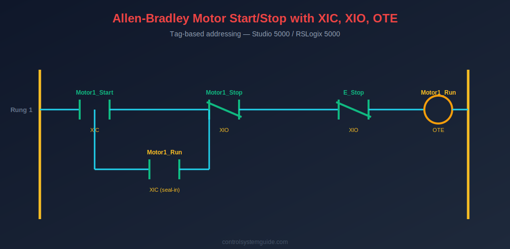
Example 1 — Motor Start/Stop with XIC, XIO, OTE Seal-In
The most fundamental Allen-Bradley ladder logic example. Uses XIC for the start button (examining if the start input is TRUE), XIO for the stop and E-stop buttons (examining if the stop inputs are FALSE — fail-safe), and OTE for the motor output coil.
| Tag Name | Data Type | Description |
|---|---|---|
| Motor1_Start | BOOL | Start push button DI |
| Motor1_Stop | BOOL | Stop push button DI (wired NC) |
| E_Stop | BOOL | Emergency stop DI (wired NC) |
| Motor1_Run | BOOL | Motor contactor DO |
Rung 1: XIC(Motor1_Start) parallel with XIC(Motor1_Run) → XIO(Motor1_Stop) → XIO(E_Stop) → OTE(Motor1_Run)
Plain English: “If Motor1_Start is pressed OR Motor1_Run is already TRUE, AND Motor1_Stop is not pressed, AND E_Stop is not pressed — then energize Motor1_Run.”
💡 Studio 5000 Tip: The Motor1_Stop tag is TRUE when the NC stop button is not pressed (input ON, contact closed). The XIO instruction passes current when this tag is TRUE — meaning the motor is allowed to run. When the button is pressed, the input goes FALSE and XIO blocks the rung.
Example 2 — Forward/Reverse Motor with Hardware Interlock
Two seal-in rungs with mutual XIO interlock contacts prevent both contactors energizing at the same time. The classic Allen-Bradley reversing starter pattern.
| Tag Name | Data Type | Description |
|---|---|---|
| Fwd_PB | BOOL | Forward start button |
| Rev_PB | BOOL | Reverse start button |
| Stop_PB | BOOL | Stop button (NC) |
| Motor_Fwd | BOOL | Forward contactor |
| Motor_Rev | BOOL | Reverse contactor |
Rung 1: XIC(Fwd_PB) parallel with XIC(Motor_Fwd) → XIO(Stop_PB) → XIO(Motor_Rev) → OTE(Motor_Fwd)
Rung 2: XIC(Rev_PB) parallel with XIC(Motor_Rev) → XIO(Stop_PB) → XIO(Motor_Fwd) → OTE(Motor_Rev)
Plain English: Each direction has its own seal-in. The XIO of the opposite direction’s output coil acts as a software interlock — neither direction can run while the other is running.
Example 3 — Jog Mode (Hold-to-Run, No Seal-In)
Motor runs only while the jog button is physically held. Used for setup and slow positioning.
Rung 1: XIC(Jog_PB) → XIO(Stop_PB) → OTE(Motor_Jog)
Plain English: No XIC of the output coil in parallel — no seal-in. The moment Jog_PB is released, the rung is FALSE and Motor_Jog drops out immediately.
OTL / OTU Latching Allen-Bradley Examples
Example 4 — Latched Alarm with Manual Reset
OTL latches an alarm ON when a fault condition occurs; OTU clears the latch when the operator presses the reset button. The alarm persists across momentary fault conditions until manually acknowledged.
| Tag Name | Data Type | Description |
|---|---|---|
| Fault_Trigger | BOOL | Fault condition input |
| Alarm_Reset_PB | BOOL | Operator reset button |
| Alarm_Latched | BOOL | Latched alarm bit |
Rung 1: XIC(Fault_Trigger) → OTL(Alarm_Latched)
Rung 2: XIC(Alarm_Reset_PB) → XIO(Fault_Trigger) → OTU(Alarm_Latched)
Plain English: Fault occurs → OTL sets Alarm_Latched and it stays ON. Reset button works only if the fault has cleared (XIO ensures fault is gone) — protecting against resetting an active fault.
Example 5 — Step Sequencer with OTL/OTU
A 3-step sequencer using latched bits to track which step is currently active. Each step latches itself ON and unlatches the previous step.
Rung 1: XIC(Cycle_Start) → OTL(Step1_Active)
Rung 2: XIC(Step1_Done) → OTL(Step2_Active), OTU(Step1_Active)
Rung 3: XIC(Step2_Done) → OTL(Step3_Active), OTU(Step2_Active)
Rung 4: XIC(Step3_Done) → OTU(Step3_Active) (cycle complete)
TON, TOF, RTO Timer Allen-Bradley Examples
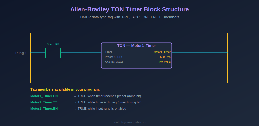
Example 6 — TON Delayed Motor Start with Warning Horn
5-second warning horn sounds before motor starts. Uses TON with a TIMER data type tag — the timer’s .DN bit becomes the start permissive for the motor.
| Tag Name | Data Type | Description |
|---|---|---|
| Start_PB | BOOL | Start button |
| Stop_PB | BOOL | Stop button (NC) |
| Motor1_Timer | TIMER | TON timer instance (PRE=5000) |
| Warning_Horn | BOOL | Warning horn output |
| Motor1_Run | BOOL | Motor contactor |
Rung 1: XIC(Start_PB) parallel with XIC(Warning_Horn) → XIO(Stop_PB) → OTE(Warning_Horn)
Rung 2: XIC(Warning_Horn) → TON(Motor1_Timer, PRE=5000ms)
Rung 3: XIC(Motor1_Timer.DN) → XIO(Stop_PB) → OTE(Motor1_Run)
Plain English: Start pressed → horn seals in → TON begins counting → after 5000ms, Motor1_Timer.DN becomes TRUE → motor starts. Stop pressed kills the horn rung, which kills the timer, which drops the motor.
Example 7 — TOF Cooling Fan Run-On
Cooling fan continues running for 120 seconds after the main motor stops. Uses TOF (Off-Delay Timer) — the timer’s .DN bit is TRUE while the input is TRUE, then stays TRUE for the preset time after the input goes FALSE.
Rung 1: XIC(Motor1_Run) → TOF(Cool_Timer, PRE=120000ms)
Rung 2: XIC(Cool_Timer.DN) → OTE(Cool_Fan)
Example 8 — RTO Retentive Runtime with RES Reset
Retentive timer tracks total motor runtime hours. Unlike TON, the accumulated value survives input transitions — only the RES instruction clears it.
Rung 1: XIC(Motor1_Run) → RTO(Runtime_Timer, PRE=36000000ms = 10000 hours)
Rung 2: XIC(Runtime_Timer.DN) → OTE(Maintenance_Due)
Rung 3: XIC(Maintenance_Done_PB) → RES(Runtime_Timer)
For complete coverage of every Allen-Bradley timer instruction, see our PLC Timer Guide.
CTU Counter Allen-Bradley Examples
Example 9 — CTU Product Counter with Batch Complete
Counts products on a conveyor; stops the line when batch count is reached. Uses COUNTER data type with .DN for the batch-complete signal.
| Tag Name | Data Type | Description |
|---|---|---|
| Product_Sensor | BOOL | Photoelectric sensor |
| Batch_Counter | COUNTER | CTU instance (PRE=100) |
| Reset_PB | BOOL | Batch reset button |
| Line_Run | BOOL | Production line output |
| Batch_Done_Lamp | BOOL | Batch complete indicator |
Rung 1: XIC(Product_Sensor) → CTU(Batch_Counter, PRE=100)
Rung 2: XIC(Reset_PB) → RES(Batch_Counter)
Rung 3: XIO(Batch_Counter.DN) → OTE(Line_Run)
Rung 4: XIC(Batch_Counter.DN) → OTE(Batch_Done_Lamp)
For complete counter coverage, see our PLC Counter Guide.
Comparison and Math Allen-Bradley Examples
Example 10 — Tank Level Control with GRT and LIM
Uses comparison instructions on an analog tank level value to control fill and drain. GRT (Greater Than), LIM (Limit) check the analog value against setpoints.
| Tag Name | Data Type | Description |
|---|---|---|
| Tank_Level | REAL | Analog tank level (0-100%) |
| Fill_Setpoint_Low | REAL | 20% — fill below this |
| Fill_Setpoint_High | REAL | 80% — stop filling above this |
| Fill_Valve | BOOL | Fill valve output |
| Auto_Mode | BOOL | Auto/manual mode |
Rung 1: XIC(Auto_Mode) → LIM(Fill_Setpoint_Low, Tank_Level, Fill_Setpoint_High) parallel with XIC(Fill_Valve) → OTE(Fill_Valve)
Plain English: In auto mode, if tank level is between 20% and 80%, allow filling. The seal-in keeps the valve open through normal level rise. Outside the range, fill stops.
Example 11 — Scaling 4-20mA to Engineering Units with CPT
Converts raw 4-20 mA input (typically 0-32767 in Studio 5000 for analog modules) into a usable engineering unit value like pressure in bar. Uses CPT (Compute) for the math.
Rung 1: XIC(Sensor_OK) → CPT(Pressure_Bar, ((Raw_Input – 6242) * 10.0) / 24902)
Plain English: Standard linear scaling — subtract the offset for 4mA, multiply by the engineering range (10 bar), divide by the count range for 4-20mA (24902 counts on a 0-32767 module). Result is pressure in bar from 0 to 10. For the underlying signal theory, see our PLC Inputs and Outputs guide.
Example 12 — Recipe Load with MOV
Loads selected recipe values into the live setpoint tags when the operator changes the recipe selection. Uses MOV instruction conditioned on a one-shot.
Rung 1: XIC(Recipe_Select_PB) → ONS(Recipe_OneShot) → MOV(Recipe1_Temp, Active_Temp_SP), MOV(Recipe1_Time, Active_Time_SP), MOV(Recipe1_Speed, Active_Speed_SP)
Plain English: When the operator selects Recipe 1, three MOV instructions copy the recipe values into the active setpoint tags — in a single scan. The ONS instruction ensures this happens exactly once per button press, not every scan while the button is held.
Allen-Bradley Tag Naming Conventions
Good tag naming is one of the things that separates professional Allen-Bradley programs from beginner code. Follow these conventions used by real-world automation engineers:
- Use descriptive names —
Motor1_StartnotI_001;Tank_LevelnotAI_03 - Use underscores or PascalCase consistently — pick one style and stay with it across the whole program
- Suffix with function —
_PBfor push buttons,_SWfor switches,_Sensorfor sensors,_Runfor motor outputs,_Alarmfor alarms - Number similar tags —
Motor1_Run,Motor2_Run,Motor3_Runfor groups of similar devices - Use base-tag structure for related data — for example a Motor1 UDT containing .Run, .Start, .Stop, .Fault, .RunHours all under one tag root
Common Allen-Bradley Ladder Logic Mistakes
1. Wrong data type for timer/counter tags. A TON instruction needs a tag of type TIMER — not BOOL, not DINT. If you create a tag as DINT and try to use it with TON, Studio 5000 throws a verification error. Always check the data type column in the Tag database before writing timer/counter rungs.
2. Confusing .DN with .EN. The .DN (done) bit becomes TRUE when the timer reaches its preset. The .EN (enable) bit is TRUE while the input rung is enabling the timer — regardless of whether it has reached preset. Beginners often use .EN where they need .DN, causing outputs to turn ON immediately instead of after the delay.
3. Double-coil OTE. Using the same tag as an OTE coil in two different rungs causes the lower rung to silently overwrite the upper rung. Each output tag gets exactly one OTE in the entire routine. If you need conditional logic, use one OTE rung with combined input logic — or use OTL/OTU latching.
4. Forgetting the RES instruction for RTO. A retentive timer (RTO) only resets when explicitly cleared with the RES instruction. If you forget the RES, the accumulator keeps growing across cycles and never clears — which is sometimes intentional (runtime tracking) but often a bug when you wanted normal TON behavior.
5. OTL without OTU. Latching a bit with OTL without programming a matching OTU somewhere means that bit can never be cleared except by a power cycle. Always pair every OTL with an OTU rung — even if the unlatch condition is just an operator reset button.
6. Using XIC where XIO is needed for stop buttons. Stop buttons in Allen-Bradley programs are typically wired Normally Closed in hardware and read with an XIO instruction in the program. The XIO is TRUE while the button is NOT pressed (input is ON). Pressing the button breaks the input and XIO blocks the rung. Using XIC instead would invert the safety behavior — confusion here causes real safety failures.
Frequently Asked Questions — Allen-Bradley Ladder Logic Examples
What does XIC mean in Allen-Bradley ladder logic?
XIC stands for Examine If Closed. It is the Allen-Bradley name for a Normally Open contact instruction. XIC evaluates TRUE when the referenced bit or input tag is ON (logic 1). When the bit is OFF, XIC blocks the rung. It is used for start buttons, sensor signals, run feedback contacts, and any “is this bit TRUE?” check.
What does XIO mean in Allen-Bradley ladder logic?
XIO stands for Examine If Open. It is the Allen-Bradley name for a Normally Closed contact instruction. XIO evaluates TRUE when the referenced bit is OFF (logic 0). It is used for stop buttons (which are typically wired NC in hardware), emergency stops, safety interlocks, and any “is this bit FALSE?” check. XIC and XIO are the logical inverse of each other.
What is the difference between OTE, OTL, and OTU?
OTE (Output Energize) is non-retentive — the output tracks the rung state every scan. When the rung goes FALSE, OTE drops the output. OTL (Output Latch) is retentive — it sets the bit ON and keeps it ON even after the rung goes FALSE. OTU (Output Unlatch) clears a latched bit when its rung is TRUE. Use OTE for normal motor and valve outputs; use OTL/OTU pairs for alarms, faults, and sequencer step flags.
How do I create a TON timer in Studio 5000?
First create a tag of data type TIMER in the Controller Tags database (for example Motor1_Timer). Then insert a TON instruction in your ladder logic, with the timer tag in the Timer field and your preset value (in milliseconds) in the Preset field. Use the timer’s .DN member as a contact in downstream rungs to act on timer completion. Example 6 in this guide shows the complete rung structure.
What is the difference between TON and RTO in Allen-Bradley?
TON (Timer On-Delay) resets its accumulated value to zero when its input goes FALSE — counting restarts from 0 the next time the input is TRUE. RTO (Retentive Timer On) keeps its accumulated value across input transitions — pausing when the input goes FALSE and resuming from the same value when the input goes TRUE again. RTO requires an explicit RES instruction to clear. Use TON for delay timing; use RTO for runtime accumulation and total-time tracking.
Are these examples compatible with RSLogix 5000?
Yes — all examples in this guide work in both RSLogix 5000 and Studio 5000 Logix Designer, which are the same software with different versioning. They are also compatible with ControlLogix, CompactLogix, FlexLogix, and SoftLogix5800 platforms. MicroLogix and SLC 500 platforms use slightly different instructions for some advanced features but the core XIC, XIO, OTE, OTL, OTU, TON, CTU instructions are identical.
Why does Allen-Bradley use tag names instead of physical addresses?
Tag-based addressing makes Allen-Bradley programs significantly more readable and maintainable than address-based platforms. A tag like Tank1_HighLevel_Switch tells you immediately what the input does — where an address like I:1/3 tells you nothing. Tags also make the program hardware-independent — moving a physical input from one channel to another only requires updating the I/O mapping, not editing every rung that uses that input. This is one of the main reasons Allen-Bradley remains the most popular PLC platform in North American industrial automation.
Conclusion
These 12 Allen-Bradley ladder logic examples cover the instructions you will use in 90% of real ControlLogix and CompactLogix programs — XIC, XIO, OTE, OTL, OTU, TON, TOF, RTO, CTU, RES, LIM, MOV, CPT, ONS. Master these patterns and you can read or write any Allen-Bradley ladder logic program at industrial scale.
Key takeaways for Allen-Bradley ladder logic:
- XIC = TRUE when ON; XIO = TRUE when OFF — the foundation of all rungs
- OTE is non-retentive; OTL stays ON until OTU clears it — choose by behavior needed
- Timer tags must be TIMER type; counter tags must be COUNTER type — wrong data type breaks compile
- Use .DN bit for “timer/counter complete” — not .EN, not .TT
- Tag-based addressing makes programs readable — invest time in good tag names upfront
Practice these examples in the free RSLogix Emulate 5000 or Studio 5000 Logix Emulate — see our PLC programming software guide for setup details. For the official Allen-Bradley instruction reference, consult the Allen-Bradley platform documentation from Rockwell Automation.
Related Guides:
- PLC Ladder Logic Tutorial – Symbols, Examples & How to Read
- Ladder Logic Symbols – Complete Reference Guide
- Ladder Logic Examples – 20 Real Industrial PLC Programs
- How to Read Ladder Logic – Step-by-Step Beginner’s Guide
- PLC Timer Explained — TON, TOF, RTO, TP
- PLC Counter Explained — CTU, CTD, CTUD
Automation engineer based in Asia, with hands-on experience in PLC programming, SCADA, and industrial control systems across oil and gas, power, food and beverage, and water industries. Writes about PLC fundamentals, ladder logic, vendor-specific instruction sets for Siemens, Allen-Bradley, and other major platforms, and industrial communication protocols.