Last Updated: May 2026 | 20 complete ladder logic examples from real industrial PLC programs, with rungs, IO lists, and plain-English explanations.
This is the most complete collection of ladder logic examples on the web — covering every common pattern you will find in real industrial PLC programs. Each example includes the rung structure, the IO list, the operating logic in plain English, and notes on how it is used in real factories. The examples work for any PLC platform — Allen-Bradley Studio 5000, Siemens TIA Portal, Mitsubishi GX Works, Omron Sysmac, and any IEC 61131-3 compliant PLC.
If you are completely new to ladder logic, start with our PLC Ladder Logic Tutorial first, then return here to dive into the example library.
In this ladder logic examples guide you will find:
- 20 complete ladder logic examples across 7 industrial categories
- Motor control — start/stop, reverse, jog, star-delta
- Timer examples — TON, TOF, flasher, retentive runtime
- Counter examples — batch counting, cycle tracking, inventory
- Conveyor and packaging control logic
- Tank, pump, and process control examples
- Safety, interlock, and traffic light sequencing
How to Use These Ladder Logic Examples
Every example below follows the same structure: a brief description of what the program does and where it is used, an IO table listing every tag, then the rung-by-rung breakdown in plain English. Read each example by applying the 5-step reading method — find the rails, identify the inputs, follow the current, identify the output, move to the next rung. If reading rungs is still new to you, see our How to Read Ladder Logic step-by-step guide.
The notation used below is generic — close to Allen-Bradley XIC/XIO/OTE conventions but readable in any platform. For the complete symbol reference including Siemens TIA Portal and IEC 61131-3 equivalents, see our Ladder Logic Symbols Guide.
Motor Control Ladder Logic Examples
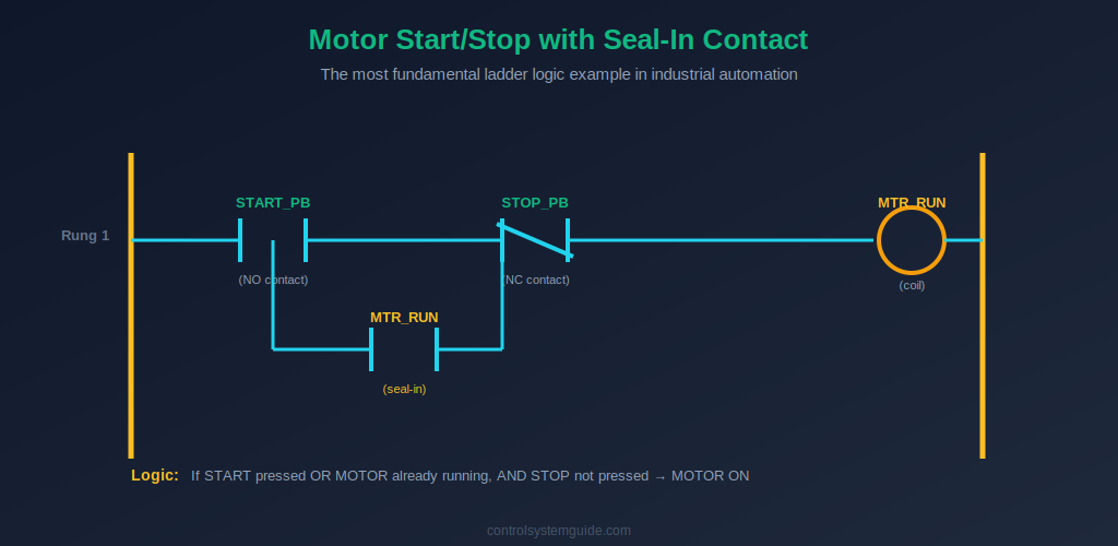
Example 1 — Basic Motor Start/Stop with Seal-In
The most fundamental ladder logic program in industrial automation. Starts a motor on a momentary push button and keeps it running through a seal-in contact until the stop button is pressed.
| Tag | Type | Description |
|---|---|---|
| START_PB | DI | Start push button (NO contact) |
| STOP_PB | DI | Stop push button (NC contact, fail-safe) |
| MTR_RUN | DO | Motor contactor coil |
Rung 1: (START_PB NO) parallel with (MTR_RUN NO) → (STOP_PB NC) → (MTR_RUN coil)
Plain English: “If START is pressed OR the motor is already running, AND STOP is not pressed — then turn the motor ON.”
Example 2 — Forward/Reverse Motor Control
Controls a motor in both directions with hardware interlock to prevent both contactors energizing simultaneously. Used in gates, hoists, and bidirectional conveyors.
| Tag | Type | Description |
|---|---|---|
| FWD_PB | DI | Forward start button |
| REV_PB | DI | Reverse start button |
| STOP_PB | DI | Stop button (NC) |
| MTR_FWD | DO | Forward contactor coil |
| MTR_REV | DO | Reverse contactor coil |
Rung 1: (FWD_PB NO) parallel with (MTR_FWD NO) → (STOP_PB NC) → (MTR_REV NC interlock) → (MTR_FWD coil)
Rung 2: (REV_PB NO) parallel with (MTR_REV NO) → (STOP_PB NC) → (MTR_FWD NC interlock) → (MTR_REV coil)
Plain English: Each direction has its own seal-in rung, and each rung includes a NC interlock contact from the opposite direction’s output — preventing the motor from running forward and reverse at the same time.
Example 3 — Jog Mode (Inch / Hold-to-Run)
The motor runs only while the jog button is held down — no seal-in. Used for setup, maintenance positioning, and slow movement.
Rung 1: (JOG_PB NO) → (STOP_PB NC) → (MTR_RUN coil)
Plain English: No seal-in contact. The moment the jog button is released, the rung goes FALSE and the motor stops.
Example 4 — Star-Delta Motor Starter
Starts a 3-phase motor in star configuration for reduced inrush current, then switches to delta after a time delay for full-speed running. Used for large motors above 7.5 kW.
| Tag | Type | Description |
|---|---|---|
| START_PB | DI | Start button |
| STOP_PB | DI | Stop button (NC) |
| K_MAIN | DO | Main contactor |
| K_STAR | DO | Star contactor |
| K_DELTA | DO | Delta contactor |
| T_STAR | TON | Star-to-delta transition timer (5-8 s) |
Rung 1: (START_PB) parallel with (K_MAIN seal-in) → (STOP_PB NC) → (K_MAIN coil)
Rung 2: (K_MAIN NO) → T_STAR (PT=6s)
Rung 3: (K_MAIN NO) → (T_STAR.Q NC) → (K_DELTA NC interlock) → (K_STAR coil)
Rung 4: (K_MAIN NO) → (T_STAR.Q NO) → (K_STAR NC interlock) → (K_DELTA coil)
Plain English: Main contactor closes on START. Star runs for 6 seconds. After the timer, star drops out and delta picks up. Star and delta are interlocked so they can never be ON simultaneously.
Timer Ladder Logic Examples
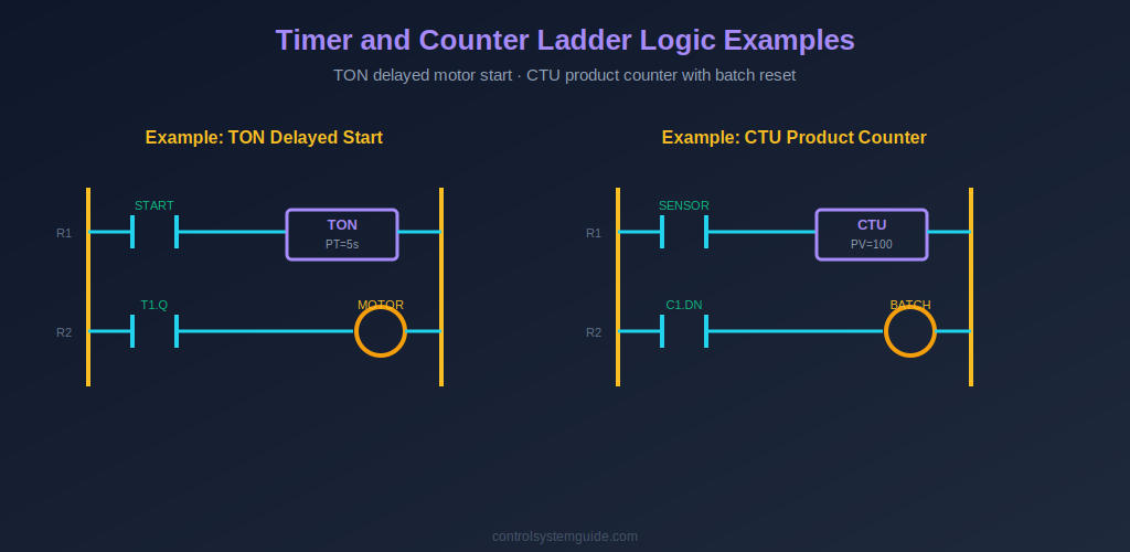
Example 5 — TON Delayed Motor Start with Warning Horn
Sounds a warning horn for 5 seconds before the motor starts. Required safety feature on crushers, large conveyors, and any machinery in an open workspace.
Rung 1: (START_PB) parallel with (HORN NO seal-in) → (STOP_PB NC) → (HORN coil)
Rung 2: (HORN NO) → T1 (TON, PT=5s)
Rung 3: (T1.Q NO) → (STOP_PB NC) → (MTR_RUN coil)
Plain English: Start pressed → horn sounds immediately and stays on → after 5 seconds, motor starts. Stop kills everything.
Example 6 — TOF Cooling Fan Run-On
Keeps a cooling fan running for 2 minutes after the main motor stops. Prevents heat damage to motors, drives, and electronic equipment.
Rung 1: (MTR_RUN NO) → T_COOL (TOF, PT=120s)
Rung 2: (T_COOL.Q NO) → (FAN_RUN coil)
Plain English: While the motor is running, the TOF input is TRUE and the fan runs. When the motor stops, TOF starts counting — fan stays on for 2 more minutes, then shuts off.
Example 7 — Flasher / Blinker Circuit
A self-oscillating circuit using two timers to flash a lamp on/off. Used for alarm indication and attention-getting visual signals.
Rung 1: (T2.Q NC) → T1 (TON, PT=0.5s)
Rung 2: (T1.Q NO) → T2 (TON, PT=0.5s)
Rung 3: (T1.Q NO) → (LAMP coil)
Plain English: Two timers chase each other in a loop, producing a 1 Hz pulse on T1.Q that drives the lamp. Output flashes on/off every half second.
Example 8 — RTO Total Motor Runtime Tracking
Retentive timer accumulates total motor runtime hours for maintenance scheduling. Survives motor stops without resetting.
Rung 1: (MTR_RUN NO) → T_RUNTIME (RTO, PT=36000000ms = 10000 hours)
Rung 2: (T_RUNTIME.Q NO) → (MAINT_ALARM coil)
Rung 3: (MAINT_DONE_PB NO) → RES T_RUNTIME (reset accumulated)
For complete coverage of all timer types, see our PLC Timer Guide.
Counter Ladder Logic Examples
Example 9 — CTU Product Counter with Batch Reset
Counts products passing a sensor and stops the production line after 100 units. Used in packaging, filling, and batch production.
Rung 1: (SENSOR NO) → C1 (CTU, PV=100) [count up input]
Rung 2: (RESET_PB NO) → RES C1
Rung 3: (C1.DN NC) → (LINE_RUN coil)
Rung 4: (C1.DN NO) → (BATCH_DONE_LAMP coil)
Plain English: Each product detected increments the counter. At 100, line stops and the batch complete lamp lights. Operator presses reset to start the next batch.
Example 10 — CTUD Parking Lot Counter
Bidirectional counter tracks cars entering and exiting a parking lot. Lights a “FULL” sign when at capacity.
Rung 1: (ENTRY_SENS NO) → C1 (CTUD, PV=500) [count up]
Rung 2: (EXIT_SENS NO) → C1 [count down]
Rung 3: (C1.QU NO) → (LOT_FULL_SIGN coil)
For complete counter coverage, see our PLC Counter Guide.
Example 11 — Cycle Counter with Maintenance Alarm
Counts machine cycles (each press, stamp, weld operation) and triggers a maintenance alarm at the configured cycle count.
Rung 1: (CYCLE_COMPLETE NO) → C_CYCLES (CTU, PV=10000)
Rung 2: (C_CYCLES.DN NO) → (MAINT_REQUIRED coil)
Rung 3: (MAINT_RESET_PB NO) → RES C_CYCLES
Conveyor and Packaging Ladder Logic Examples
Example 12 — Conveyor with Product Detection and Jam Alarm
Conveyor runs when product is detected, stops at end limit, and triggers an alarm if a jam is detected anywhere along the belt.
Rung 1: (PHOTO_SENS NO) parallel with (CONV_RUN NO seal-in) → (END_LIMIT NC) → (JAM_DETECT NC) → (CONV_RUN coil)
Rung 2: (JAM_DETECT NO) → (JAM_ALARM coil)
Plain English: Product detected → conveyor runs and seals in → stops at end limit → alarm if jam detected.
Example 13 — Reject Gate with Counter
Counts defective products detected by a quality sensor and pulses a reject gate solenoid for 500ms to push the defect off the belt.
Rung 1: (REJECT_SENS NO) → C_REJECTS (CTU)
Rung 2: (REJECT_SENS NO) → T_PULSE (TON, PT=500ms)
Rung 3: (REJECT_SENS NO) → (T_PULSE.Q NC) → (REJECT_GATE coil)
Example 14 — Three-Motor Sequential Start
Motors start in sequence with 5-second delays to prevent product pileups on multi-belt conveyor systems.
Rung 1: (START_PB) parallel with (M1 seal-in) → (STOP_PB NC) → (M1 coil)
Rung 2: (M1 NO) → T1 (TON, PT=5s)
Rung 3: (T1.Q NO) → (STOP_PB NC) → (M2 coil)
Rung 4: (M2 NO) → T2 (TON, PT=5s)
Rung 5: (T2.Q NO) → (STOP_PB NC) → (M3 coil)
Tank, Pump, and Process Ladder Logic Examples
Example 15 — Tank Fill Control with High/Low Level
Fill valve opens when the tank is below low level, closes when the tank reaches high level. The classic bang-bang level control loop using two switches.
Rung 1: (LOW_LEVEL NO) parallel with (FILL_VALVE NO seal-in) → (HIGH_LEVEL NC) → (AUTO_MODE NO) → (FILL_VALVE coil)
Plain English: When level drops below low setpoint, fill valve opens and seals in. Valve stays open until the high-level switch trips. Auto mode permissive prevents fill in manual mode.
Example 16 — Duplex Pump Control (Lead-Lag)
Two pumps share duty — one runs as lead, the other as standby. Alternates between pumps after each cycle to equalize wear.
Rung 1: (PUMP_CALL NO) → (P1_LEAD NO) → (P1_RUN coil)
Rung 2: (PUMP_CALL NO) → (P1_LEAD NC) → (P2_RUN coil)
Rung 3: (PUMP_CALL rising edge ONS) → toggle P1_LEAD bit
Plain English: Each call alternates which pump is the lead. P1 runs first call, P2 next call, P1 again, and so on.
Example 17 — Sump Pump with Low-Level Protection
Sump pump runs when water rises to the high level switch and stops at the low level switch. Includes a dry-run protection that disables the pump if the low level fails to clear within 30 seconds.
Rung 1: (HIGH_SW NO) parallel with (PUMP_RUN NO seal-in) → (LOW_SW NO) → (DRY_RUN_FAULT NC) → (PUMP_RUN coil)
Rung 2: (PUMP_RUN NO) → (LOW_SW NC) → T_DRYRUN (TON, PT=30s)
Rung 3: (T_DRYRUN.Q NO) → (DRY_RUN_FAULT Set coil)
Safety and Interlock Ladder Logic Examples
Example 18 — Emergency Stop with Latching Reset
E-stop trips a latched fault that requires manual reset before the machine can run again. Standard pattern for any machine with hazardous motion.
Rung 1: (E_STOP NC) → (E_STOP_FAULT Reset coil OTU)
Rung 2: (E_STOP NO) → (E_STOP_FAULT Set coil OTL)
Rung 3: (RESET_PB NO) → (E_STOP NC) → (E_STOP_FAULT Reset OTU)
Rung 4: (E_STOP_FAULT NC) → (MACHINE_READY coil)
Plain English: E-stop pressed → fault latched. Even after E-stop is released, the fault stays latched. Operator must press reset (with E-stop already released) to clear the fault and allow the machine to run.
Example 19 — Two-Hand Safety Press Start
Press cycle requires both hands on buttons within 500ms of each other — preventing one-handed operation that could leave the other hand in the danger zone.
Rung 1: (LEFT_PB NO) → T_LEFT (TON, PT=500ms)
Rung 2: (RIGHT_PB NO) → T_RIGHT (TON, PT=500ms)
Rung 3: (LEFT_PB NO) → (RIGHT_PB NO) → (T_LEFT.Q NC) → (T_RIGHT.Q NC) → (PRESS_CYCLE coil)
Plain English: Both buttons must be pressed within 500ms of each other. If either button is held more than 500ms before the other is pressed, the rung blocks — preventing taped-down or cheat-button operation.
Sequential Control Ladder Logic Example
Example 20 — Traffic Light Sequence
A classic teaching example — automatic single-direction traffic light cycling through Green (20s) → Yellow (4s) → Red (20s).
| Tag | Type | Description |
|---|---|---|
| RUN_MODE | DI | System enable switch |
| T_GREEN | TON | Green light timer (20s) |
| T_YELLOW | TON | Yellow light timer (4s) |
| T_RED | TON | Red light timer (20s) |
| GREEN, YELLOW, RED | DO | Three light outputs |
Rung 1: (RUN_MODE NO) → (T_RED.Q NC) → (GREEN coil) and start T_GREEN
Rung 2: (T_GREEN.Q NO) → (T_YELLOW.Q NC) → (YELLOW coil) and start T_YELLOW
Rung 3: (T_YELLOW.Q NO) → (T_RED.Q NC) → (RED coil) and start T_RED
Rung 4: When T_RED.Q goes TRUE → all timers reset → cycle restarts at Green
Plain English: Green for 20s → Yellow for 4s → Red for 20s → repeat. Each phase enables the next via its done bit, and the cycle resets when the red timer completes.
How These Ladder Logic Examples Translate to Real Vendors
The 20 examples above use generic notation. Here is how the symbols translate to the two most common PLC platforms:
| Generic in examples | Allen-Bradley Studio 5000 | Siemens TIA Portal |
|---|---|---|
| NO contact | XIC | –| |– |
| NC contact | XIO | –|/|– |
| Output coil | OTE | –( )– |
| Set / Latch | OTL | –(S)– |
| Reset / Unlatch | OTU | –(R)– |
| TON timer | TON instruction with TIMER tag | TON with Instance DB |
| CTU counter | CTU instruction with COUNTER tag | CTU with Instance DB |
| RES (reset) | RES instruction | R input on timer/counter block |
The underlying logic is identical. Only the symbol naming and the timer/counter instance handling differ. For platform-specific tutorials, see our PLC programming software guide.
Frequently Asked Questions — Ladder Logic Examples
What is the most common ladder logic example?
The motor start/stop circuit with a seal-in contact (Example 1) is the most common ladder logic example in industrial automation. It appears in virtually every factory PLC program — controlling motors, pumps, fans, conveyors, and any output that needs to stay ON after a momentary start input. Understanding this single rung is the foundation of all ladder logic programming.
What is a seal-in contact in ladder logic?
A seal-in contact is an auxiliary NO contact of the output coil placed in parallel with the start input. When the start button is pressed, the output energizes — and the seal-in contact closes in parallel, keeping the rung TRUE even after the start button is released. The seal-in maintains the output until a stop condition breaks the series chain.
How do I write a ladder logic program for a motor with timer?
Use a TON (on-delay) timer in series with the motor output rung. Place a NO contact of the start input as the timer input. After the preset time, the timer’s done bit (T.Q) turns ON — use a NO contact of T.Q in series with the motor output to start the motor after the delay. Example 5 in this guide shows the complete rung structure.
What ladder logic examples should a beginner learn first?
Start with these five examples in order: (1) basic motor start/stop with seal-in, (2) forward/reverse with interlock, (3) TON delayed start, (4) CTU product counter with reset, (5) tank fill with high/low level. These five cover 80% of the logic patterns you will encounter in real PLC programs. Once comfortable, move on to the safety, sequencing, and traffic light examples.
Are these ladder logic examples Siemens or Allen-Bradley?
The examples use generic IEC 61131-3 notation that works for both Allen-Bradley Studio 5000 and Siemens TIA Portal. Only the instruction names and tag addressing differ between vendors — the rung structure and logic flow are identical. The conversion table earlier in this guide shows exactly how each generic symbol maps to Allen-Bradley XIC/XIO/OTE and Siemens graphical notation.
Can I download these ladder logic examples as a PDF?
The full set of 20 ladder logic examples is available free on this page — use your browser’s print-to-PDF function to save a copy for offline reference. Each example includes the IO list, rung structure, and plain-English explanation so you can adapt it directly to your own PLC project.
What is the difference between latch and seal-in in ladder logic?
A seal-in uses a standard output coil (OTE) with an auxiliary contact in parallel with the start input — the output drops out as soon as any series contact opens. A latch uses a Set coil (OTL) that keeps the output ON even after the rung goes FALSE, and requires a separate Reset coil (OTU) on another rung to clear it. Seal-ins are used for motor control; latches are used for alarms and persistent flags.
Conclusion
These 20 ladder logic examples cover the patterns you will encounter in over 90% of real industrial PLC programs. The motor start/stop seal-in, the TON delayed start, the CTU batch counter, the conveyor jam detection, the tank fill, the duplex pump alternation, the E-stop latching, the two-hand safety, and the traffic light sequence — these are the building blocks every automation engineer uses every day.
Key takeaways:
- Master the motor start/stop seal-in first — it appears in every PLC program
- Combine timers with seal-ins for delayed start, run-on, and flashers
- Use counters with reset for batch control and cycle tracking
- Use latching (OTL/OTU) for faults and alarms that must persist after the cause clears
- Always interlock opposing outputs like forward/reverse and star/delta
Practice these examples in a free simulator like CODESYS or LogixPro — see our PLC programming software guide for recommendations. The international standard that defines all PLC programming notation is IEC 61131-3.
Related Guides:
- PLC Ladder Logic Tutorial – Symbols, Examples & How to Read
- Ladder Logic Symbols – Complete Reference Guide
- How to Read Ladder Logic – Step-by-Step Beginner’s Guide
- PLC Timer Explained — TON, TOF, RTO, TP
- PLC Counter Explained — CTU, CTD, CTUD
- PLC Inputs and Outputs — DI, DO, AI, AO Explained
Automation engineer based in Asia, with hands-on experience in PLC programming, SCADA, and industrial control systems across oil and gas, power, food and beverage, and water industries. Writes about PLC fundamentals, ladder logic, vendor-specific instruction sets for Siemens, Allen-Bradley, and other major platforms, and industrial communication protocols.