Last Updated: May 2026 | 12 complete Siemens ladder logic examples in TIA Portal with %I/%Q addressing and Instance Data Blocks.
This guide is a complete library of Siemens ladder logic examples written in TIA Portal LAD (Ladder Diagram) language. Every example uses Siemens conventions — %I for inputs, %Q for outputs, %M for memory bits, symbolic tag names from the PLC Tag table, and Instance Data Blocks for timers and counters. The examples work on S7-1200, S7-1500, S7-300, and S7-400 controllers programmed in TIA Portal V15 or later.
If you are completely new to PLC programming, start with our PLC Ladder Logic Tutorial first. For the matching guide using Allen-Bradley conventions, see Allen-Bradley Ladder Logic Examples.
In this Siemens ladder logic examples guide you will find:
- 12 complete Siemens ladder logic examples in TIA Portal LAD
- Motor control with NO/NC contacts and output coils
- Set/Reset (–(S)–, –(R)–) latching for alarms
- TON, TOF, TP timers with Instance DBs
- CTU, CTD, CTUD counters with Instance DBs
- Comparison and math — ==, <, >, ADD, MOVE
- How %I/%Q addressing and symbolic tags work together
How Siemens Ladder Logic Differs From Other Platforms
Siemens TIA Portal uses three conventions that distinguish it from Allen-Bradley Studio 5000 and other PLC platforms:
1. Graphical symbols, no mnemonic instruction names. Where Allen-Bradley uses XIC, XIO, OTE as instruction names, Siemens uses the IEC 61131-3 graphical symbols directly. A Normally Open contact is just --| |--. A Normally Closed contact is --|/|--. An output coil is --( )--. There is no separate mnemonic — the symbol is the instruction.
2. Mixed addressing — %I/%Q with symbolic tags. Siemens uses absolute addresses like %I0.0 (input bit 0 of byte 0) and %Q0.0 (output bit 0 of byte 0). These addresses are mapped to symbolic tag names like “Start_PB” or “Motor_Run” in the PLC Tags table. In the program you can write either the absolute address or the symbolic name — TIA Portal displays both. Memory bits use %M, data block bits use %DB1.DBX0.0.
3. Instance Data Blocks for every timer and counter. This is the biggest structural difference from Allen-Bradley. Each TON, TOF, TP, CTU, CTD, CTUD instance in your Siemens program requires its own dedicated Instance Data Block (Instance DB). When you drop a TON into a network, TIA Portal prompts you to create a new DB or assign an existing one. The DB stores the timer’s PT, ET, IN, Q values. You reference timer outputs as "Instance_DB_Name".Q — not as a separate done-bit tag.
For complete platform comparison side-by-side, see our Ladder Logic Symbols Guide.
Motor Control Siemens Ladder Logic Examples
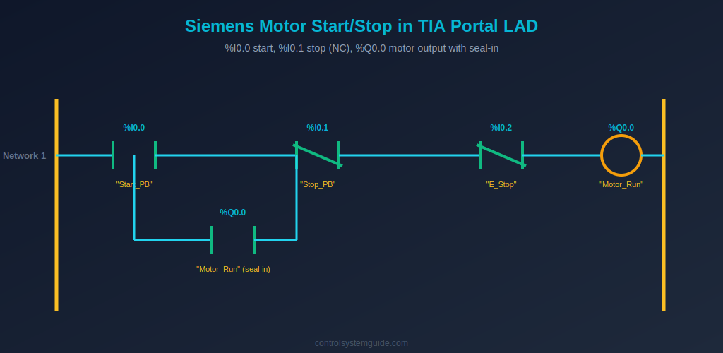
Example 1 — Motor Start/Stop with Seal-In
The most fundamental Siemens ladder logic example. Uses NO contact for start, NC contact for stop and E-stop (matching the fail-safe physical wiring), an output coil for the motor, and a parallel NO contact of the output as seal-in.
| Symbolic Tag | Address | Data Type | Description |
|---|---|---|---|
| “Start_PB” | %I0.0 | Bool | Start push button DI |
| “Stop_PB” | %I0.1 | Bool | Stop push button DI (wired NC) |
| “E_Stop” | %I0.2 | Bool | Emergency stop DI (wired NC) |
| “Motor_Run” | %Q0.0 | Bool | Motor contactor DO |
Network 1: –| |–“Start_PB” parallel with –| |–“Motor_Run” → –|/|–“Stop_PB” → –|/|–“E_Stop” → –( )–“Motor_Run”
Plain English: “If Start_PB is pressed OR Motor_Run is already TRUE, AND Stop_PB is not pressed, AND E_Stop is not pressed — then energize Motor_Run.”
💡 TIA Portal Tip: Stop_PB is TRUE while the field button is NOT pressed (NC contact closed, input ON). The –|/|– contact in the program passes current when the underlying tag is FALSE. So you wire NC in the field and use NC in the program — and the motor stops both when the button is pressed AND if the cable breaks. This is fail-safe behavior.
Example 2 — Forward/Reverse Motor with Software Interlock
Two seal-in networks with mutual NC interlock contacts prevent both contactors energizing simultaneously.
| Symbolic Tag | Address | Description |
|---|---|---|
| “Fwd_PB” | %I0.0 | Forward start button |
| “Rev_PB” | %I0.1 | Reverse start button |
| “Stop_PB” | %I0.2 | Stop button (NC) |
| “Motor_Fwd” | %Q0.0 | Forward contactor |
| “Motor_Rev” | %Q0.1 | Reverse contactor |
Network 1: –| |–“Fwd_PB” parallel with –| |–“Motor_Fwd” → –|/|–“Stop_PB” → –|/|–“Motor_Rev” → –( )–“Motor_Fwd”
Network 2: –| |–“Rev_PB” parallel with –| |–“Motor_Rev” → –|/|–“Stop_PB” → –|/|–“Motor_Fwd” → –( )–“Motor_Rev”
Plain English: Each direction has its own seal-in. The NC contact of the opposite direction’s output coil acts as a software interlock — neither direction can run while the other is running.
Example 3 — Jog Mode (No Seal-In)
Motor runs only while jog button is physically held. Used for setup and slow positioning movements.
Network 1: –| |–“Jog_PB” → –|/|–“Stop_PB” → –( )–“Motor_Jog”
Plain English: No NO contact of the output in parallel — no seal-in. The moment Jog_PB is released, the network is FALSE and Motor_Jog drops out immediately.
Set / Reset Latching Siemens Examples
Example 4 — Latched Alarm with Manual Reset
Set coil –(S)– latches an alarm ON when a fault occurs. Reset coil –(R)– clears the latch when the operator presses reset (and the fault has cleared). The alarm persists across momentary fault conditions.
| Symbolic Tag | Address | Description |
|---|---|---|
| “Fault_Trigger” | %I0.5 | Fault condition input |
| “Alarm_Reset_PB” | %I0.6 | Operator reset button |
| “Alarm_Latched” | %M0.0 | Latched alarm memory bit |
Network 1: –| |–“Fault_Trigger” → –(S)–“Alarm_Latched”
Network 2: –| |–“Alarm_Reset_PB” → –|/|–“Fault_Trigger” → –(R)–“Alarm_Latched”
Plain English: Fault occurs → Set coil latches Alarm_Latched ON and it stays ON. Reset button works only if the fault has cleared — protecting against resetting an active fault.
Example 5 — Step Sequencer with SR Flip-Flop Logic
A 3-step sequencer using Set/Reset coils to track which step is currently active.
Network 1: –| |–“Cycle_Start” → –(S)–“Step1_Active”
Network 2: –| |–“Step1_Done” → –(S)–“Step2_Active”; –| |–“Step1_Done” → –(R)–“Step1_Active”
Network 3: –| |–“Step2_Done” → –(S)–“Step3_Active”; –| |–“Step2_Done” → –(R)–“Step2_Active”
Network 4: –| |–“Step3_Done” → –(R)–“Step3_Active” (cycle complete)
TON, TOF, TP Timer Siemens Examples
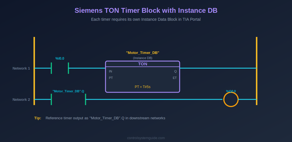
Example 6 — TON Delayed Motor Start with Warning Horn
5-second warning horn sounds before motor starts. Uses TON with its dedicated Instance DB — the timer’s Q output becomes the start permissive for the motor.
| Symbolic Tag / Block | Address / Type | Description |
|---|---|---|
| “Start_PB” | %I0.0 / Bool | Start button |
| “Stop_PB” | %I0.1 / Bool | Stop button (NC) |
| “Motor_Timer_DB” | Instance DB (TON) | Timer instance, PT = T#5s |
| “Warning_Horn” | %Q0.1 / Bool | Warning horn output |
| “Motor_Run” | %Q0.0 / Bool | Motor contactor |
Network 1: –| |–“Start_PB” parallel with –| |–“Warning_Horn” → –|/|–“Stop_PB” → –( )–“Warning_Horn”
Network 2: –| |–“Warning_Horn” → TON (“Motor_Timer_DB”, PT=T#5s)
Network 3: –| |–“Motor_Timer_DB”.Q → –|/|–“Stop_PB” → –( )–“Motor_Run”
Plain English: Start pressed → horn seals in → TON begins counting → after 5 seconds, “Motor_Timer_DB”.Q becomes TRUE → motor starts. Pressing stop kills the horn network, which drops the timer input, which drops the motor.
Example 7 — TOF Cooling Fan Run-On
Cooling fan continues running for 2 minutes after the main motor stops. Uses TOF — the timer’s Q output is TRUE while input is TRUE, then stays TRUE for the preset time after input goes FALSE.
Network 1: –| |–“Motor_Run” → TOF (“Cool_Timer_DB”, PT=T#2m)
Network 2: –| |–“Cool_Timer_DB”.Q → –( )–“Cool_Fan”
Example 8 — TP Pulse Timer for Fixed-Duration Output
Generates a fixed 500ms pulse to the reject gate solenoid whenever a defective product is detected — regardless of how long the sensor pulse lasts.
Network 1: –| |–“Defect_Sensor” → TP (“Reject_Pulse_DB”, PT=T#500ms)
Network 2: –| |–“Reject_Pulse_DB”.Q → –( )–“Reject_Gate”
Plain English: Defect detected → TP fires → output stays ON for exactly 500ms then automatically drops. Subsequent detections retrigger the pulse only after the current one completes.
For complete coverage of all Siemens timer types and timing diagrams, see our PLC Timer Guide.
CTU and CTUD Counter Siemens Examples
Example 9 — CTU Product Counter with Batch Complete
Counts products on a conveyor; stops the line when batch count is reached. Each CTU instance needs its own Instance DB exposing CV (current value), Q (done bit), and PV (preset).
| Symbolic Tag / Block | Address / Type | Description |
|---|---|---|
| “Product_Sensor” | %I0.3 / Bool | Photoelectric sensor |
| “Batch_Counter_DB” | Instance DB (CTU) | Counter instance, PV = 100 |
| “Reset_PB” | %I0.4 / Bool | Batch reset button |
| “Line_Run” | %Q0.0 / Bool | Production line output |
| “Batch_Done_Lamp” | %Q0.1 / Bool | Batch complete indicator |
Network 1: –| |–“Product_Sensor” → CTU (“Batch_Counter_DB”, PV=100, R=”Reset_PB”)
Network 2: –|/|–“Batch_Counter_DB”.Q → –( )–“Line_Run”
Network 3: –| |–“Batch_Counter_DB”.Q → –( )–“Batch_Done_Lamp”
Note: Siemens CTU has a built-in R (reset) input — no separate RES instruction needed like in Allen-Bradley.
Example 10 — CTUD Bidirectional Parking Counter
Up/down counter tracks cars entering and exiting a parking lot. Increments on entry sensor, decrements on exit sensor. Lights a “FULL” sign at capacity.
Network 1: CTUD (“Parking_DB”, CU=”Entry_Sens”, CD=”Exit_Sens”, PV=500)
Network 2: –| |–“Parking_DB”.QU → –( )–“Lot_Full_Sign”
For complete counter coverage, see our PLC Counter Guide.
Comparison and Data Siemens Examples
Example 11 — Tank Level Control with IN_RANGE Comparison
Uses comparison instructions on an analog tank level value to control fill behavior. Siemens uses graphical compare boxes (==, <, >, IN_RANGE) instead of Allen-Bradley’s EQU, LIM mnemonics.
| Symbolic Tag | Data Type | Description |
|---|---|---|
| “Tank_Level” | Real | Analog tank level 0-100% |
| “Fill_SP_Low” | Real | 20% — fill below this |
| “Fill_SP_High” | Real | 80% — stop above this |
| “Fill_Valve” | Bool | Fill valve output |
| “Auto_Mode” | Bool | Auto / manual selector |
Network 1: –| |–“Auto_Mode” → [Tank_Level < Fill_SP_Low compare] parallel with –| |–“Fill_Valve” → [Tank_Level < Fill_SP_High compare] → –( )–“Fill_Valve”
Plain English: In auto mode, if tank level drops below 20%, open the fill valve. Seal in the valve until level reaches 80%. Outside auto mode, this network has no effect.
Example 12 — MOVE Instruction for Recipe Load
Loads selected recipe values into the active setpoint tags when the operator changes recipe selection. Uses MOVE instruction conditioned on a P-trigger (rising edge).
Network 1: –|P|–“Recipe_Select_PB” → MOVE(“Recipe1.Temp” IN → “Active_Temp_SP” OUT)
Network 2: –|P|–“Recipe_Select_PB” → MOVE(“Recipe1.Time” IN → “Active_Time_SP” OUT)
Plain English: On the rising edge of the recipe select button, MOVE copies recipe values into the live setpoint tags. The P trigger (–|P|–) ensures this happens exactly once per button press, not every scan.
Siemens TIA Portal Tag Naming Conventions
Professional Siemens programs use consistent tag naming across the PLC Tag table. Follow these conventions used in real-world automation projects:
- Use symbolic names — “Motor1_Start” not just “%I0.0”; the symbolic name is what shows in your networks
- Suffix with function type — _PB for push buttons, _SW for switches, _Sensor for sensors, _Run for motor outputs, _Alarm for alarms
- Group with prefixes — Pump1_Run, Pump1_Start, Pump1_Stop, Pump1_Fault all share the “Pump1_” prefix for easy filtering
- Name Instance DBs consistently — “Motor1_Timer_DB” not “DB1”; the DB name appears wherever the timer is referenced in downstream networks
- Use User-Defined Data Types (UDTs) for repeating structures — define a “Motor” UDT containing .Run, .Start, .Stop, .Fault, .Hours and instantiate it for each motor
Common Siemens Ladder Logic Mistakes
1. Forgetting to create the Instance DB. Every TON, TOF, TP, CTU, CTD, CTUD instance needs its own Instance DB. When you drop the instruction into a network, TIA Portal prompts you — do not skip this. Reusing the same Instance DB across multiple timers causes them to interfere with each other and produce unpredictable results.
2. Confusing %Q (output) with %M (memory). %Q addresses map to physical output channels. %M addresses are internal memory bits that do not drive any hardware. Beginners sometimes use %M where they need %Q, then wonder why the motor never starts. Always check whether you want a physical output or an internal flag.
3. Double-coil –( )–. Using the same tag as an output coil in two different networks causes the lower network to silently overwrite the upper one. Each output tag gets exactly one –( )– coil in the entire program block. For multiple conditions driving one output, combine the conditions into a single network using parallel branches.
4. Wrong PT data type. Timer preset values use the TIME data type with format T#5s, T#500ms, T#2m, T#1h30m. Beginners sometimes try to enter raw numbers like 5000 — which causes compile errors. Use TIA Portal’s literal syntax (T# prefix) or define a TIME constant.
5. Set –(S)– without Reset –(R)–. Latching a bit with –(S)– without programming a matching –(R)– means that bit can never be cleared except by a power cycle (and not always then, if it is in retentive memory). Always pair every Set with a Reset network — even if the reset condition is just an operator acknowledgment button.
6. Mixing absolute address and symbolic name in the same expression. TIA Portal allows you to type either %I0.0 or “Start_PB” and displays both. But editing the address directly when the symbolic name is already mapped can break the link between them. Best practice: always edit through the PLC Tag table, not by typing in the network.
Frequently Asked Questions — Siemens Ladder Logic Examples
What is LAD in Siemens TIA Portal?
LAD stands for Ladder Diagram — one of the five PLC programming languages defined by IEC 61131-3 and supported in Siemens TIA Portal. LAD is the graphical ladder logic language using contacts (–| |–, –|/|–), output coils (–( )–), and function blocks (TON, CTU, etc.) arranged on networks between two vertical power rails. It is the most widely used programming language for Siemens S7-1200, S7-1500, S7-300, and S7-400 controllers.
What does %I0.0 mean in Siemens ladder logic?
%I0.0 is a Siemens absolute address referring to bit 0 of input byte 0 — the first digital input on the PLC. The % symbol marks an absolute address, I designates the input area, 0.0 is the byte and bit. Other prefixes: %Q for outputs (%Q0.0), %M for internal memory bits (%M10.0), %DB for data block bits (%DB1.DBX0.0). Each absolute address is typically mapped to a symbolic name like “Start_PB” in the PLC Tag table.
Do I need a separate Instance DB for every timer in Siemens?
Yes — each TON, TOF, TP timer instance requires its own dedicated Instance Data Block. The Instance DB stores the timer’s current state (IN input, PT preset, ET elapsed, Q output). Reusing the same Instance DB across multiple timers makes them share state and produce incorrect behavior. When you drop a timer block into a network, TIA Portal automatically prompts you to create or assign an Instance DB.
What is the difference between Siemens LAD and Allen-Bradley ladder logic?
The core logic is identical — both follow IEC 61131-3 standards. The differences are: (1) Siemens uses graphical symbols without instruction mnemonics, while Allen-Bradley uses XIC, XIO, OTE, OTL, OTU; (2) Siemens addresses use %I/%Q with optional symbolic tags, while Allen-Bradley is fully tag-based; (3) Siemens timers and counters require Instance Data Blocks, while Allen-Bradley uses TIMER and COUNTER data type tags directly in the rung. For both platforms, the rung structure and logic flow are the same.
Can I use these examples on S7-1200 and S7-1500?
Yes — all 12 examples work on S7-1200, S7-1500, S7-300, and S7-400 controllers programmed in TIA Portal V15 or later. The S7-1200 and S7-1500 use the modern IEC timer instructions (TON, TOF, TP) exactly as shown in the examples. S7-300 and S7-400 can use these same IEC timers or the legacy S_ODT / S_PEXT timers — both are supported in TIA Portal for backward compatibility.
What is the difference between Set –(S)– and –( )– in Siemens LAD?
The standard output coil –( )– tracks the network state every scan — when the network is TRUE the output is ON, when the network goes FALSE the output drops out. The Set coil –(S)– latches the bit ON when the network is TRUE and keeps it ON even after the network goes FALSE. Use –( )– for normal motor and valve outputs; use –(S)– paired with –(R)– (Reset) for alarms and fault flags that must persist until manually acknowledged.
How do I reset a CTU counter in Siemens?
The CTU counter block in Siemens has a dedicated R (reset) input — connect any boolean signal to the R pin and the counter clears to zero when that signal is TRUE. There is no separate RES instruction needed (unlike Allen-Bradley). For Example 9 in this guide, “Reset_PB” connects directly to the CTU’s R input, clearing the batch counter when the operator presses the reset button.
Conclusion
These 12 Siemens ladder logic examples cover the patterns you will use in 90% of real S7-1200, S7-1500, S7-300, and S7-400 programs — NO/NC contacts, output coils, Set/Reset latching, TON/TOF/TP timers with Instance DBs, CTU/CTD/CTUD counters, IN_RANGE comparisons, and MOVE for data transfers. Master these and you can read or write any Siemens TIA Portal LAD program at industrial scale.
Key takeaways for Siemens ladder logic:
- %I for inputs, %Q for outputs, %M for memory bits — the address foundations
- NO –| |– is TRUE when ON; NC –|/|– is TRUE when OFF — the contact rule
- –( )– tracks the network; –(S)– latches; –(R)– clears — coil behaviors
- Every timer and counter needs its own Instance DB — never reuse
- Always map symbolic tags in the PLC Tag table — keeps programs readable
Practice these examples in the free PLCSIM Advanced simulator that comes with TIA Portal — see our PLC programming software guide for setup details. For the official Siemens LAD reference, consult the Siemens PLC documentation in TIA Portal Information System.
Related Guides:
- PLC Ladder Logic Tutorial – Symbols, Examples & How to Read
- Allen-Bradley Ladder Logic Examples — XIC, XIO, OTE in Studio 5000
- Ladder Logic Symbols – Complete Reference Guide
- Ladder Logic Examples – 20 Real Industrial PLC Programs
- How to Read Ladder Logic – Step-by-Step Beginner’s Guide
- PLC Timer Explained — TON, TOF, RTO, TP
- PLC Counter Explained — CTU, CTD, CTUD
Automation engineer based in Asia, with hands-on experience in PLC programming, SCADA, and industrial control systems across oil and gas, power, food and beverage, and water industries. Writes about PLC fundamentals, ladder logic, vendor-specific instruction sets for Siemens, Allen-Bradley, and other major platforms, and industrial communication protocols.