Last Updated: April 2026 | Written for automation engineers and beginners learning PLC programming.
A PLC timer is one of the most important and most used instructions in industrial automation programming. Every automation engineer needs to master timers — from a simple 5-second motor start delay to complex multi-step production sequences.
In this complete guide you will find:
- All 4 IEC 61131-3 PLC timer types explained clearly — TON, TOF, RTO, TP
- Timing diagrams showing exactly when each timer input and output changes
- 7 real industrial ladder logic examples using timers
- How timers work in Siemens TIA Portal and Allen-Bradley Studio 5000
- Full timer parameter reference — PRE, ACC, EN, TT, DN bits explained
- The most common timer mistakes and how to avoid them
What Is a PLC Timer?
A PLC timer is a software instruction that introduces a time delay into ladder logic programs. It monitors an input condition, starts counting when that condition changes, and triggers an output after a preset time has elapsed.
PLC timers replaced traditional timer relays — mechanical or electronic timing devices that were wired into relay control panels. A PLC timer does the same job entirely in software, with no moving parts, no wiring, and the ability to change the preset time instantly through programming software.
The IEC 61131-3 standard defines 3 standard PLC timer types — TON, TOF, and TP. Allen-Bradley adds a fourth — RTO (Retentive Timer). All 4 are widely used in real industrial projects.
💡 Key Concept: A PLC timer does NOT pause the scan cycle. The PLC continues scanning all rungs at normal speed while the timer counts. The timer simply sets its output bits when the accumulated time reaches the preset value.
PLC Timer Parameters — What Each Value Means
Before learning each timer type, you need to understand the parameters every PLC timer uses:
| Parameter | Name | Type | Description |
|---|---|---|---|
| PRE / PT | Preset Time | Input | The target time the timer counts to. When ACC reaches PRE, the timer done bit activates. |
| ACC / ET | Accumulated Time | Output | The current elapsed time. Counts up from 0 to PRE during timing. |
| EN | Enable Bit | Output | ON when the timer rung is TRUE (input condition is active). |
| TT | Timer Timing Bit | Output | ON while the timer is actively counting (EN is TRUE and ACC < PRE). |
| DN / Q | Done Bit | Output | ON when ACC has reached PRE. This is the main output bit used in ladder logic. |
| Time Base | Resolution | Input | The counting resolution — typically 1ms, 10ms, 100ms, or 1s depending on PLC brand. |
💡 Rockwell vs Siemens Naming: Allen-Bradley uses PRE and ACC. Siemens IEC timers use PT (Preset Time) and ET (Elapsed Time). The function is identical — only the names differ.
PLC Timer Timing Diagrams
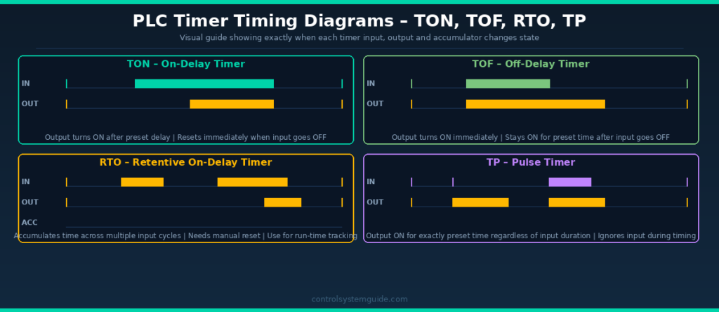
1. TON Timer – On-Delay Timer (Most Used)
The TON (Timer On-Delay) is the most widely used PLC timer instruction in industrial automation. It introduces a delay between an input going TRUE and its output activating. The output only turns ON after the input has been continuously TRUE for the full preset time.
How TON Works
- Input goes TRUE → timer starts counting from 0
- ACC counts up toward PRE
- When ACC reaches PRE → DN bit turns ON → output activates
- Input goes FALSE at any time → timer resets to 0 immediately → DN bit turns OFF
- If input goes FALSE before timer reaches PRE → timer resets with no output
TON in Rockwell Studio 5000 (Allen-Bradley)
| Parameter | Tag | Example Value |
|---|---|---|
| Timer Tag | Motor_Start_Delay | TIMER data type |
| Preset | Motor_Start_Delay.PRE | 5000 (= 5 seconds at 1ms base) |
| Accum | Motor_Start_Delay.ACC | 0 to 5000 |
| Done Bit | Motor_Start_Delay.DN | TRUE when 5s elapsed |
TON in Siemens TIA Portal
| Parameter | Tag | Example Value |
|---|---|---|
| Timer DB | “Motor_TON” | IEC_TIMER instance DB |
| IN (Input) | %I0.0 | Start signal |
| PT (Preset) | T#5S | 5 seconds |
| ET (Elapsed) | “Motor_TON”.ET | Current elapsed time |
| Q (Done) | “Motor_TON”.Q | TRUE after 5 seconds |
When to Use TON
- Delayed motor start (warning before machine starts)
- Alarm delay (alarm only activates if fault persists for set time)
- Conveyor start sequence delays
- Heating element activation after temperature setpoint delay
- Debouncing noisy sensor signals
2. TOF Timer – Off-Delay Timer
The TOF (Timer Off-Delay) works opposite to the TON. The output turns ON immediately when the input goes TRUE. When the input goes FALSE, the timer starts counting — and the output stays ON for the preset time before turning OFF.
How TOF Works
- Input goes TRUE → output turns ON immediately (no delay)
- Input goes FALSE → timer starts counting from 0
- ACC counts up toward PRE while output remains ON
- When ACC reaches PRE → DN bit turns OFF → output turns OFF
- If input goes TRUE again before timer expires → timer resets, output stays ON
When to Use TOF
- Motor run-on after stop command (fan continues after motor stops)
- Lubrication pump continues after machine stops
- Cooling fan runs on for set time after heater turns off
- Conveyor clears products after stop command
- Hydraulic system maintains pressure after valve closes
💡 Real Example: A cooling fan on a motor control cabinet must continue running for 3 minutes after the main motor stops — to prevent heat damage. TOF with a 180-second preset achieves this perfectly. Motor stop signal → fan stays ON → 3 minutes later → fan stops.
3. RTO Timer – Retentive On-Delay Timer
The RTO (Retentive Timer On-Delay) is a special timer that accumulates time across multiple input cycles. Unlike TON which resets when the input goes FALSE, the RTO retains its accumulated value when the input goes FALSE. It only resets when a separate Reset (RES) instruction is triggered.
How RTO Works
- Input goes TRUE → timer starts counting, ACC increases
- Input goes FALSE → timer stops but ACC value is retained (not reset)
- Input goes TRUE again → timer continues from where ACC left off
- When total accumulated time reaches PRE → DN bit turns ON
- Only resets when a separate RES instruction is executed
When to Use RTO
- Tracking total motor run time for maintenance scheduling
- Monitoring total machine cycle time
- Measuring total time a valve has been open
- Production time tracking across shifts
- Maintenance alert after total operating hours reached
💡 Important Note: In Siemens TIA Portal, the equivalent of RTO is TONR (Timer On-Delay Retentive). In IEC 61131-3 standard, it is also called TONR. The function is identical to Rockwell RTO — only the name differs.
4. TP Timer – Pulse Timer
The TP (Pulse Timer) generates a fixed-length output pulse when its input is triggered. The output turns ON for exactly the preset time regardless of how long the input stays ON. During timing, new input signals are ignored — the pulse runs to completion.
How TP Works
- Input goes TRUE → output turns ON immediately, timer starts
- Output stays ON for exactly the preset time
- Input going FALSE during timing has no effect
- New input signals during timing are ignored
- After preset time → output turns OFF, timer ready for next trigger
When to Use TP
- Solenoid valve pulse (open for exactly 2 seconds)
- Indicator lamp flash (on for exactly 500ms)
- Injection moulding shot timer (exact shot duration)
- Dosing pump activation (fixed dose time)
- One-shot output trigger from a momentary input
PLC Timer Types Comparison
| Feature | TON | TOF | RTO | TP |
|---|---|---|---|---|
| IEC Name | TON | TOF | TONR | TP |
| Rockwell Name | TON | TOF | RTO | Not standard |
| Siemens Name | TON | TOF | TONR | TP |
| Output ON when | After input ON delay | Immediately on input | After accumulated time | Immediately on input |
| Output OFF when | Input goes OFF | After input OFF delay | Manual reset only | After preset time |
| Resets when | Input goes FALSE | ACC reaches PRE | RES instruction only | After preset time |
| Retentive? | No | No | Yes | No |
| Most common use | Start delays | Run-on delays | Run-time totals | Fixed pulses |
| Industry usage | ⭐⭐⭐⭐⭐ Most used | ⭐⭐⭐⭐ Common | ⭐⭐⭐ Moderate | ⭐⭐⭐ Moderate |
7 Real PLC Timer Examples
Example 1 – Motor Start Warning Horn (TON)
A conveyor motor must not start without a 5-second warning horn sounding first. This is a safety requirement in most manufacturing facilities.
| Tag | Type | Description |
|---|---|---|
| START_PB | DI | Start push button |
| STOP_PB | DI | Stop push button (NC) |
| WARNING_HORN | DO | Warning horn output |
| CONV_RUN | DO | Conveyor motor output |
| START_TIMER | TON | 5 second delay, PRE=5000 |
Rung 1: START_PB (NO) + CONV_RUN seal-in → STOP_PB (NC) → WARNING_HORN output (horn sounds immediately)
Rung 2: START_PB (NO) + CONV_RUN seal-in → STOP_PB (NC) → TON Timer (PT=5s)
Rung 3: START_TIMER.DN (NO) → CONV_RUN output (motor starts after 5s)
Example 2 – Cooling Fan Run-On After Motor Stop (TOF)
An electric motor generates heat during operation. The cooling fan must continue running for 3 minutes after the motor stops to prevent thermal damage.
Rung 1: MOTOR_RUN (NO) → TOF Timer (PT=180s)
Rung 2: COOL_TIMER.Q (NO) → COOLING_FAN output
When MOTOR_RUN turns OFF → TOF starts → COOLING_FAN stays ON → after 180 seconds → fan stops.
Example 3 – Alarm Delay (TON)
A pressure transmitter triggers an alarm only if pressure stays high for more than 10 seconds — preventing nuisance alarms from momentary pressure spikes.
Rung 1: PRESS_HIGH (NO) → TON Timer (PT=10s)
Rung 2: PRESS_TIMER.DN (NO) → PRESS_ALARM output
Example 4 – Motor Run-Time Maintenance Alert (RTO)
A pump motor needs bearing maintenance after every 2,000 hours of operation. The RTO tracks total run time and triggers a maintenance alarm.
Rung 1: PUMP_RUN (NO) → RTO Timer (PRE = 7,200,000,000ms = 2,000 hours)
Rung 2: RUN_TIMER.DN (NO) → MAINT_ALARM output
Rung 3: MAINT_RESET_PB (NO) → RES instruction (resets RTO timer)
Example 5 – Dosing Valve Pulse (TP)
A chemical dosing valve must open for exactly 2 seconds each time a batch starts — regardless of how long the batch start signal is held.
Rung 1: BATCH_START (NO) → TP Timer (PT=2s)
Rung 2: DOSE_TIMER.Q (NO) → DOSE_VALVE output
Example 6 – Three-Motor Sequence Start (TON Chain)
Three motors must start in sequence — Motor 1 immediately, Motor 2 after 5 seconds, Motor 3 after 10 seconds. Used in conveyor systems to prevent overloading the electrical supply.
Rung 1: START_PB → MTR1_RUN (Motor 1 starts immediately)
Rung 2: MTR1_RUN (NO) → TON Timer T1 (PT=5s)
Rung 3: T1.DN (NO) → MTR2_RUN (Motor 2 starts after 5s)
Rung 4: MTR2_RUN (NO) → TON Timer T2 (PT=5s)
Rung 5: T2.DN (NO) → MTR3_RUN (Motor 3 starts after 10s total)
Example 7 – Flashing Alarm Lamp (TON Self-Resetting)
An alarm lamp must flash at 1 second ON / 1 second OFF to indicate a fault condition. This is achieved using a self-resetting TON timer.
Rung 1: FAULT_ACTIVE (NO) → FLASH_TIMER.TT (NC) → TON Timer FLASH_TIMER (PT=1s)
Rung 2: FAULT_ACTIVE (NO) → FLASH_TIMER.DN (NO) → RES FLASH_TIMER (resets timer when done)
Rung 3: FAULT_ACTIVE (NO) → FLASH_TIMER.TT (NO) → ALARM_LAMP output
The timer continuously resets itself creating a 1-second ON / 1-second OFF flash cycle.
Common PLC Timer Mistakes
Mistake 1 – Wrong time base calculation
In older Allen-Bradley PLCs (SLC 500, PLC-5), the preset value depends on the time base setting. If time base is 0.01s and you want 5 seconds, preset = 500. If time base is 1.0s, preset = 5. Modern Studio 5000 and TIA Portal use milliseconds directly — always verify which system you are using.
Mistake 2 – Using TON when TOF is needed
A very common mistake is using a TON to create a run-on delay. TON turns ON after a delay — TOF stays ON after the input turns OFF. Always draw a timing diagram first to confirm which behaviour you need.
Mistake 3 – Forgetting to reset the RTO
The RTO timer never resets automatically. If you forget to add a Reset (RES) rung for the RTO, the accumulated time will reach the preset once and the DN bit will stay permanently ON until someone manually resets it through the programming software.
Mistake 4 – Duplicate timer addresses
In older fixed-address PLCs (SLC 500), if you use the same timer address (e.g., T4:0) in two different rungs, both rungs will control the same timer — causing unpredictable behaviour. Each timer instruction must have a unique address or tag.
Mistake 5 – Incorrect time units in TIA Portal
Siemens TIA Portal uses the TIME data type for timer presets. The format is T#5S for 5 seconds, T#500MS for 500 milliseconds, T#2M for 2 minutes. Entering a number without the T# prefix will cause a compile error.
PLC Timer Instructions by Brand
| Timer Type | Allen-Bradley | Siemens TIA Portal | Mitsubishi | Omron |
|---|---|---|---|---|
| On-Delay | TON | TON | OUT T (K value) | TIM |
| Off-Delay | TOF | TOF | Not standard | TIMH |
| Retentive | RTO | TONR | Not standard | TTIM |
| Pulse | Not standard | TP | Not standard | Not standard |
| Time base | 1ms (Studio 5000) | T#xS / T#xMS | 100ms or 10ms | 100ms default |
| Done bit | .DN | .Q | T contact | T contact |
Frequently Asked Questions – PLC Timer
What is a PLC timer?
A PLC timer is a software instruction used in ladder logic programming to introduce a time delay. It monitors an input condition, counts elapsed time, and activates an output after a preset time has been reached. PLC timers replaced traditional mechanical and electronic timer relays in industrial control panels.
What is the difference between TON and TOF timers?
A TON (On-Delay) timer delays turning ON — the output activates after the input has been ON for the preset time. A TOF (Off-Delay) timer delays turning OFF — the output activates immediately when the input turns ON, then stays ON for the preset time after the input turns OFF. TON is used for start delays, TOF is used for run-on delays.
What is a retentive timer in PLC?
A retentive timer (called RTO in Allen-Bradley, TONR in Siemens) accumulates elapsed time across multiple input cycles. Unlike a standard TON timer which resets when the input goes FALSE, a retentive timer retains its accumulated value until a separate Reset instruction clears it. It is used for tracking total machine run time and maintenance scheduling.
How do you set a PLC timer preset?
In Allen-Bradley Studio 5000, the preset is set in milliseconds in the PRE field of the TIMER tag — for example 5000 for 5 seconds. In Siemens TIA Portal, the preset uses the TIME data type with the format T#5S for 5 seconds, T#500MS for 500 milliseconds, or T#2M30S for 2 minutes 30 seconds.
What is the TON timer done bit?
The Done bit (DN in Allen-Bradley, Q in Siemens) is the main output bit of a PLC timer. It turns ON when the accumulated time reaches the preset time. The Done bit is used as a contact in other rungs to trigger actions after the timer completes. In Allen-Bradley, it is accessed as TimerTag.DN. In Siemens TIA Portal, it is accessed as “TimerDB”.Q.
Can you use multiple timers in one PLC program?
Yes. Modern PLCs support hundreds or thousands of timer instructions in a single program. Each timer must have a unique tag name (Studio 5000) or unique instance data block (TIA Portal). You can use as many timers as needed — a large industrial program may have hundreds of TON, TOF, and RTO instructions across many program blocks.
What is the difference between RTO and TON timers?
A TON timer resets its accumulated value to zero whenever the input goes FALSE. An RTO timer retains its accumulated value when the input goes FALSE, and continues from where it left off when the input goes TRUE again. TON is used when you need a delay from a continuous signal. RTO is used when you need to accumulate total time from intermittent signals, such as tracking total machine run hours.
What is a TP pulse timer in PLC?
A TP (Pulse) timer generates a fixed-length output pulse. When its input triggers, the output turns ON for exactly the preset time regardless of what the input does during timing. This makes it ideal for applications requiring a precise, fixed-duration output — such as a solenoid valve that must open for exactly 2 seconds, or a dosing pump that must run for a fixed time per cycle.
Conclusion
PLC timers are essential in every industrial automation program. Mastering all four timer types — TON, TOF, RTO, and TP — gives you the ability to control any time-based process in industrial automation.
To summarize when to use each:
- TON — when you need a delay before something turns ON (most common)
- TOF — when you need something to stay ON for a set time after a signal turns OFF
- RTO — when you need to accumulate total time across multiple cycles
- TP — when you need a fixed-length output pulse from a trigger signal
Related Guides:
- PLC Ladder Logic Tutorial – 7 Real Industrial Examples
- PLC Programming Languages – All 5 IEC 61131-3 Languages
- PLC Inputs and Outputs – DI, DO, AI, AO Explained
- What Is a PLC? Complete Beginner’s Guide
Automation engineer based in Asia, with hands-on experience in PLC programming, SCADA, and industrial control systems across oil and gas, power, food and beverage, and water industries. Writes about PLC fundamentals, ladder logic, vendor-specific instruction sets for Siemens, Allen-Bradley, and other major platforms, and industrial communication protocols.