Last Updated: April 2026 | Written for automation engineers and project managers selecting PLC hardware for industrial projects.
PLC IO calculation is the most important first step before selecting any automation hardware. Calculating the i/o count for a PLC determines which model you need, how many expansion modules to buy, what panel size to design, and ultimately how much your project will cost.
Getting the PLC IO calculation wrong leads to either an undersized PLC that runs out of capacity during commissioning, or an oversized PLC that wastes thousands of dollars in unused capacity. The total i/o count determines which PLC model you need, how many expansion modules to buy, what panel size to design, and ultimately how much your project will cost. Getting the i/o count wrong leads to either an undersized PLC that runs out of capacity during commissioning, or an oversized PLC that wastes thousands of dollars in unused capacity.
This complete PLC i/o calculation guide explains exactly how to count, calculate and verify the i/o count for any industrial automation project — using the proven 5-step method used by automation engineers worldwide.
In this PLC i/o count calculation guide you will learn:
- What i/o count means in PLC selection and why it is critical
- The proven 5-step method to calculate i/o count for any project
- The exact i/o count formula used by professional engineers
- A complete worked example showing i/o count for a real conveyor system
- How spare i/o capacity protects you from costly system upgrades
- Common i/o count mistakes beginners make and how to avoid them
- I/o count ranges for different project sizes with PLC recommendations
- How to use a free PLC i/o template to speed up the calculation
What Is I/O Count in PLC Selection?
The i/o count is the total number of input and output signals connecting a PLC to all field devices in a control system. Every individual sensor, switch, transmitter, motor, valve and lamp in the system counts as exactly one i/o point. The i/o count is the foundation of every PLC selection decision — it determines CPU sizing, module quantity, panel design and total project cost.
| Signal Type | What Counts as 1 I/O Point | Real Field Device Examples |
|---|---|---|
| Digital Input (DI) | Each ON/OFF sensor or switch | Push button, limit switch, proximity sensor, level switch, E-stop button |
| Digital Output (DO) | Each ON/OFF actuator or indicator | Motor contactor coil, solenoid valve, indicator lamp, alarm horn |
| Analog Input (AI) | Each variable signal sensor | Pressure transmitter, temperature transmitter, flow meter, level transmitter |
| Analog Output (AO) | Each variable signal control device | Control valve positioner, VFD speed reference, dosing pump |
💡 Key Concept: The i/o count is always calculated before selecting PLC hardware — never after. Estimating i/o count during the design phase is the foundation of accurate project costing, panel sizing, and PLC selection. A small 30-minute investment in proper i/o count calculation prevents 80% of common automation project problems.
The 5-Step I/O Count Calculation Method
Follow these 5 steps in order to calculate the exact i/o count for any automation project. Skipping any step leads to undersized PLCs or missed signals during commissioning.
Step 1 — List Every Sensor and Switch (Digital Inputs)
Walk through your machine or process and identify every device that sends an ON/OFF signal to the PLC. Count each device as one digital input. Do not group devices together — each push button, each limit switch, each proximity sensor gets its own dedicated i/o point.
| Device Category | Examples | Common in |
|---|---|---|
| Operator inputs | Start button, Stop button, Reset button, Selector switches | Every machine |
| Safety devices | Emergency stop, Light curtain, Safety door switch, Two-hand control | All industrial systems |
| Position sensors | Limit switches, Proximity sensors, Photoelectric sensors | Conveyors, machines |
| Process switches | Pressure switch, Temperature switch, Level switch, Flow switch | Tank systems, hydraulics |
| Feedback signals | Motor running auxiliary, Drive ready, Valve position confirmation | Motor control circuits |
Step 2 — List Every Actuator and Output Device (Digital Outputs)
Now identify every device the PLC will control with an ON/OFF signal. Each motor contactor coil, each solenoid valve, each indicator lamp counts as one digital output point.
| Device Category | Examples | Typical Voltage |
|---|---|---|
| Motor control | Contactor coils, Motor starter coils, Brake release solenoids | 24VDC or 230VAC |
| Pneumatic devices | Solenoid valves, Pneumatic cylinder pilots, Air blast valves | 24VDC typical |
| Indicators | Status lamps, Tower lights, Beacon lights, LED indicators | 24VDC |
| Alarm devices | Buzzer, Siren, Strobe light, Horn | 24VDC or 230VAC |
| Heating elements | SSR control to heater banks, Bandheater enable | Via SSR or relay |
Step 3 — List Every Analog Sensor and Transmitter (Analog Inputs)
Identify every device that sends a variable signal to the PLC — typically 4-20mA or 0-10V. Each transmitter counts as one analog input channel. Most PLC analog input modules have 4 or 8 channels.
| Sensor Type | Signal Format | What It Measures |
|---|---|---|
| Pressure transmitter | 4-20mA or 0-10V | Pressure in bar, PSI, kPa |
| Temperature transmitter | 4-20mA, RTD or thermocouple | Temperature in °C, °F |
| Flow meter | 4-20mA or pulse | Flow rate in L/min, m³/h |
| Level transmitter | 4-20mA | Level in % or meters |
| Position feedback | 4-20mA from LVDT or potentiometer | Position in mm or % |
| Load cell amplifier | 4-20mA or 0-10V | Weight in kg or tons |
Step 4 — List Every Modulating Control Device (Analog Outputs)
Identify every device the PLC controls with a variable signal. Control valves, VFD speed references, and modulating dampers all need analog output channels.
| Control Device | Signal Format | Function |
|---|---|---|
| Control valve positioner | 4-20mA | Modulates valve from 0% closed to 100% open |
| VFD speed reference | 4-20mA or 0-10V | Sets motor speed via variable frequency drive |
| Dosing pump | 4-20mA or pulse | Controls chemical dosing flow rate |
| Modulating damper | 0-10V to actuator | HVAC airflow control |
| Heater output | 4-20mA to SCR controller | Proportional heating control |
Step 5 — Add Spare I/O Capacity and Calculate Total
After listing all four signal types, add 20-25% spare i/o capacity to each total. This spare capacity protects against scope creep, late design changes, and future system expansion. Without spare capacity, even small modifications require a complete PLC hardware upgrade.
The I/O Count Formula
Total I/O Count = (DI + DO + AI + AO) × 1.25
Where the multiplier 1.25 represents the standard 25% spare i/o capacity. Some engineers use 1.20 (20% spare) for tightly budgeted projects, or 1.30 (30% spare) for projects with high uncertainty. 25% is the industry standard for balancing cost and flexibility.
Why 25% Spare I/O Capacity Is Industry Standard
| Reason | What Happens Without Spare | Cost If Missing |
|---|---|---|
| Scope changes during design | Customer adds 2 sensors after PLC ordered | $500-2000 to add expansion module |
| Site discovery during installation | Existing equipment needs 4 extra signals | $1000-3000 in delays and rework |
| Future system expansion | Cannot add new feature without PLC upgrade | $5000-15000 full PLC replacement |
| Safety system additions | New safety regulations require extra inputs | $2000-8000 retrofit cost |
| Diagnostic signals added later | Need to monitor extra parameters | $500-2000 module addition |
I/O Count Calculation – Worked Example

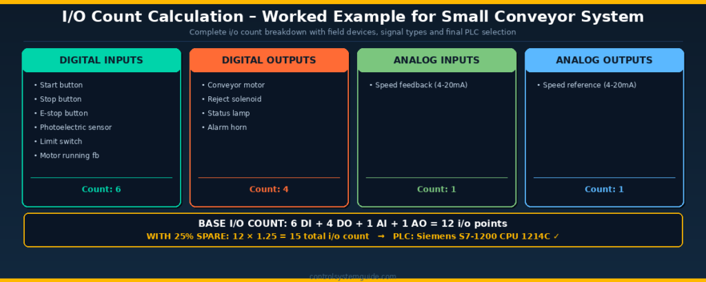
Here is a complete i/o count calculation example for a typical small conveyor automation system that detects products, runs the conveyor at variable speed, rejects defective items, and signals operator status.
| Field Device | I/O Type | Signal | Count |
|---|---|---|---|
| Start button (NO push button) | Digital Input | 24VDC | 1 |
| Stop button (NC push button) | Digital Input | 24VDC | 1 |
| Emergency stop (NC E-stop) | Digital Input | 24VDC | 1 |
| Photoelectric sensor (item detect) | Digital Input | 24VDC PNP | 1 |
| Limit switch (conveyor end) | Digital Input | 24VDC | 1 |
| Motor running auxiliary contact | Digital Input | 24VDC | 1 |
| Conveyor motor contactor coil | Digital Output | 24VDC | 1 |
| Reject solenoid valve coil | Digital Output | 24VDC | 1 |
| Running status lamp | Digital Output | 24VDC | 1 |
| Alarm horn | Digital Output | 24VDC | 1 |
| VFD speed feedback (4-20mA) | Analog Input | 4-20mA | 1 |
| VFD speed reference (4-20mA) | Analog Output | 4-20mA | 1 |
I/O Count Summary
| Signal Type | Base Count | With 25% Spare |
|---|---|---|
| Digital Inputs (DI) | 6 | 8 (rounded up) |
| Digital Outputs (DO) | 4 | 5 (rounded up) |
| Analog Inputs (AI) | 1 | 2 (minimum 2 for redundancy) |
| Analog Outputs (AO) | 1 | 2 (minimum 2 for redundancy) |
| TOTAL I/O COUNT | 12 | 17 i/o points |
Recommended PLC Based on I/O Count
For an i/o count of 17 points, a compact PLC such as the Siemens S7-1200 CPU 1214C is the perfect match. The CPU 1214C includes 14 digital inputs, 10 digital outputs, and 2 analog inputs built in — easily handling this i/o count with room for additional expansion modules if the project grows. Read our complete Siemens S7-1200 Tutorial for setup details.
I/O Count Ranges by Project Size
Here is a quick reference of typical i/o count ranges and recommended PLC hardware for different project sizes:
| Project Size | Typical I/O Count | Recommended PLC | Real Examples |
|---|---|---|---|
| Small machine | 10-30 i/o | Compact PLC — S7-1200, Allen Bradley Micro850 | Single conveyor, simple machine, dosing system |
| Medium machine | 30-100 i/o | Compact + expansion modules | Packaging line, filling machine, mixing tank |
| Production line | 100-500 i/o | Modular PLC — S7-1500, CompactLogix 5380 | Bottling line, assembly station, batch reactor |
| Large plant | 500-2000 i/o | Modular with remote IO — ControlLogix, S7-1500 | Process plant section, automotive line |
| Plant-wide system | 2000+ i/o | DCS or distributed PLC architecture | Refinery, chemical plant, pharmaceutical facility |
Common I/O Count Calculation Mistakes
| Mistake | Why It Matters | How to Avoid It |
|---|---|---|
| Forgetting safety devices | E-stops, safety relays, light curtains add 4-8 inputs minimum | Always list all safety devices first in step 1 |
| Skipping spare i/o capacity | System cannot expand without buying new PLC hardware | Always add 20-25% spare to final i/o count |
| Wiring multiple devices in series | Cannot identify which device caused a fault — troubleshooting nightmare | Each device gets its own dedicated i/o point |
| Mixing voltage types on one module | Modules support 24VDC OR 120VAC — not both on the same module | Group same-voltage devices on the same i/o module |
| Missing analog signals | Each transmitter needs its own analog input channel | Identify all 4-20mA, 0-10V, RTD signals separately in step 3 |
| Not counting feedback signals | Motor running feedback, valve position feedback need extra inputs | For each output device check if feedback is needed |
| Ignoring HMI requirements | HMI may need extra signals beyond machine control | Review HMI screens during i/o count calculation |
| Forgetting communication signals | VFDs, drives, smart sensors may need network connections | List EtherNet/IP, PROFINET, Modbus devices separately |
Free Excel Template for I/O Count Calculation
For larger projects with dozens of signals, manual i/o count calculation becomes time-consuming. The free PLC IO List Excel template helps you organize all signals in one structured spreadsheet, with separate columns for DI, DO, AI, and AO. Apply the 25% spare capacity formula to the column totals to get your
recommended PLC size.
The template includes:
- Columns for DI, DO, AI, AO signal types
- Tag name, description, and address fields
- Cable number and engineering notes
- One row per signal — easy to count totals at the bottom
👉 👉 Download Free PLC IO List Excel Template
I/O Count vs IO List – What Is the Difference?
| Aspect | I/O Count | IO List |
|---|---|---|
| What it is | The total number of i/o points | A detailed table of every i/o point with full information |
| Used for | PLC selection and sizing | Wiring, panel design, programming, commissioning |
| Detail level | Just numbers — DI, DO, AI, AO totals | Tag name, description, address, voltage, cable, module slot |
| When created | Concept and quotation phase | Detailed engineering phase |
| Document type | Single calculation summary | Excel spreadsheet with 50+ columns |
For a complete IO list template and 7 worked examples, read our companion guide: PLC IO List – Free Excel Template + 7 Real Examples
Frequently Asked Questions – PLC I/O Count Calculation
What is i/o count in a PLC?
The i/o count in a PLC is the total number of input and output signals connecting the PLC to all field devices in a control system. The i/o count includes every digital input, digital output, analog input, and analog output that the PLC must read or control. Each individual sensor, switch, transmitter, motor, valve, and lamp counts as one i/o point. The i/o count is the most important parameter for selecting the correct PLC model and sizing the automation system.
How do you calculate i/o count for a PLC?
To calculate the i/o count for a PLC follow 5 steps. First list every sensor and switch — these are digital inputs. Second list every actuator, motor and lamp — these are digital outputs. Third list every transmitter and analog instrument — these are analog inputs. Fourth list every modulating control device like control valves and VFDs — these are analog outputs. Fifth add 20-25% spare capacity to each total. The final i/o count formula is (DI + DO + AI + AO) × 1.25.
What is the formula for PLC i/o count calculation?
The standard formula is Total I/O Count = (DI + DO + AI + AO) × 1.25 where DI is digital inputs, DO is digital outputs, AI is analog inputs, AO is analog outputs, and the multiplier 1.25 represents 25% spare capacity for future expansion. Some projects use 1.20 for tighter budgets or 1.30 for high uncertainty applications. The i/o count formula gives the total number of points the selected PLC must support.
How much spare i/o capacity should be added?
Industry standard practice is to add 20-25% spare i/o capacity to the calculated base i/o count. This spare capacity allows for scope changes during design, late additions during installation, future system expansion, and unexpected modifications discovered during commissioning. Adding less than 15% spare capacity often results in expensive PLC hardware upgrades within 1-2 years of system installation. Critical or rapidly evolving systems may use 30% spare capacity.
What is a typical i/o count for a small automation project?
Small automation projects such as single conveyors, simple machines, or basic dosing systems typically have an i/o count of 10-30 points. Medium projects like packaging lines and filling machines have 30-100 i/o. Large production lines and process units have 100-500 i/o. Plant-wide systems exceed 500 i/o and often use multiple PLCs in distributed architecture. The i/o count directly determines whether a compact, modular, or distributed PLC architecture is required.
What PLC should I select based on i/o count?
For i/o count under 30 points choose a compact PLC like Siemens S7-1200 or Allen Bradley Micro850. For i/o count of 30-100 points use a compact PLC with expansion modules. For i/o count of 100-500 points choose a modular PLC like Siemens S7-1500 or Allen Bradley CompactLogix 5380. For i/o count above 500 points use a full modular system like Allen Bradley ControlLogix 5580 with remote i/o racks. Always select a PLC with at least 25% capacity above your calculated i/o count.
What is the difference between i/o count and io list?
The i/o count is just the total number of input and output points — used for PLC selection and project costing. The io list is a detailed table containing every i/o point with complete information including tag name, description, address, voltage type, cable specification, and PLC module slot — used for wiring, panel design, programming, and commissioning. The i/o count is calculated first during the concept phase. The io list is created during detailed engineering after the PLC has been selected.
Why is i/o count important in PLC selection?
The i/o count is the foundation of every PLC selection decision because it directly determines CPU sizing, module quantity, panel design space requirements, power supply rating, and total project cost. An undersized PLC requires expensive replacement when the i/o count exceeds capacity. An oversized PLC wastes budget on unused capacity. The i/o count must be calculated accurately during the concept phase to enable correct hardware selection and reliable project costing before any quotation is issued to the customer.
Conclusion
Accurate i/o count calculation is the foundation of every successful automation project. The 5-step method ensures no signals are missed, the 25% spare capacity rule protects against costly upgrades, and proper PLC selection based on i/o count prevents both undersizing and overspending.
Key points to remember about PLC i/o count calculation:
- I/O count = total input and output points connecting the PLC to all field devices
- 5-step method: sensors → actuators → analog inputs → analog outputs → spare capacity
- Formula: Total i/o count = (DI + DO + AI + AO) × 1.25
- Always add 20-25% spare i/o capacity for future expansion
- I/O count determines PLC selection — compact, modular, or distributed architecture
- Use a free PLC i/o template for projects with dozens of signals
Related Guides:
- PLC IO List – Free Excel Template + 7 Real Examples
- PLC IO List Example – 5 Real Industrial Cases
- PLC Inputs and Outputs – DI, DO, AI, AO Complete Guide
- Compact vs Modular PLC – Decision Guide
- Siemens S7-1200 Tutorial – Complete Beginner Guide
Automation engineer based in Asia, with hands-on experience in PLC programming, SCADA, and industrial control systems across oil and gas, power, food and beverage, and water industries. Writes about PLC fundamentals, ladder logic, vendor-specific instruction sets for Siemens, Allen-Bradley, and other major platforms, and industrial communication protocols.