Last Updated: April 2026 | Real industrial cases used by automation engineers worldwide.
A PLC IO list example is the fastest way for automation engineers to learn how to organize PLC signals in a real industrial project. Rather than reading abstract theory, seeing a complete PLC IO list example with actual tag names, signal types, and PLC addresses helps you understand the structure used by professional control engineers across every industry. Rather than reading abstract theory, seeing a complete i/o list example with actual tag names, signal types, and PLC addresses helps you understand the structure used by professional control engineers across every industry.
This guide presents 5 complete i/o list examples taken from real industrial automation projects — covering motor control, tank systems, conveyors, packaging machines, and water treatment plants. Each i/o list example includes the full signal table with all 12 required columns ready to use as a template for your own projects.
The terms i/o list and io list are interchangeable in industry — both refer to the same document used during PLC project design and commissioning. This guide uses both spellings throughout because both versions appear in real engineering practice worldwide.
In this i/o list example guide you will learn:
- What an i/o list example looks like in real industrial automation projects
- The 12 essential columns every PLC i/o list example must contain
- 5 complete real i/o list examples from different industries
- How to customize an i/o list example for your own automation project
- The most common mistakes engineers make when building an i/o list
- How to download a free i/o list example template in Excel format
What Is an I/O List Example?

An i/o list example is a documented signal table from a real industrial automation project showing how engineers organize every input and output connected to a PLC. A complete i/o list example contains every digital input, digital output, analog input, and analog output along with critical reference data — tag numbers, descriptions, PLC addresses, cable numbers, and engineering units.
The i/o list example serves multiple purposes across the project lifecycle. Control engineers use it to write the PLC program logic. Electrical engineers use it to design the panel wiring. Commissioning engineers use it to test every signal during system startup. Maintenance teams use it for fault finding throughout the system’s operational life.
| Phase | How the I/O List Example Is Used | Engineering Team |
|---|---|---|
| Design phase | Define PLC size, IO modules, panel layout, cable schedule | System integrator, electrical designer |
| Programming phase | Create PLC tags, write control logic, configure HMI screens | Control engineer, programmer |
| Wiring phase | Terminate field cables, label terminals, build the panel | Panel builder, electrician |
| Commissioning phase | Test each signal one-by-one, verify correct function | Commissioning engineer |
| Operation phase | Reference document for fault finding and maintenance | Maintenance technician |
💡 Why I/O List Examples Matter: Every successful automation project starts with a clean i/o list example. Engineers who skip this document inevitably face wiring mistakes, programming errors, and costly delays during commissioning. A 2-hour investment in building a proper i/o list example saves 20+ hours during project execution.
The 12 Essential Columns in Any I/O List Example
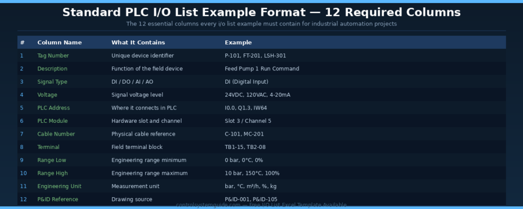
Every professional i/o list example contains the same 12 essential columns regardless of industry or PLC platform. Some large projects extend the format to 16-21 columns for additional commissioning and maintenance data, but these 12 columns form the foundation of every i/o list example used worldwide.
| # | Column Name | What It Contains | Example Value |
|---|---|---|---|
| 1 | Tag Number | Unique device identifier following plant tag philosophy | P-101, FT-201, LSH-301 |
| 2 | Description | Function of the field device in plain language | Feed Pump 1 Run Command |
| 3 | Signal Type | DI / DO / AI / AO classification | DI (Digital Input) |
| 4 | Voltage | Electrical signal voltage level | 24VDC, 120VAC, 4-20mA |
| 5 | PLC Address | Where the signal connects in the PLC tag database | I0.0, Q1.3, IW64 |
| 6 | PLC Module | Hardware slot and channel reference | Slot 3 / Channel 5 |
| 7 | Cable Number | Physical cable identification reference | C-101, MC-201 |
| 8 | Terminal | Field terminal block where signal lands | TB1-15, TB2-08 |
| 9 | Range Low | Engineering range minimum value | 0 bar, 0°C, 0% |
| 10 | Range High | Engineering range maximum value | 10 bar, 150°C, 100% |
| 11 | Engineering Unit | Measurement unit | bar, °C, m³/h, %, kg |
| 12 | P&ID Reference | Source drawing where the device appears | P&ID-001, P&ID-105 |
I/O List Example 1 – Motor Control System
This i/o list example is the most common in industrial automation. The motor control i/o list example covers conveyor motors, pump motors, compressors, fans, and any other rotating equipment. Almost every PLC project includes at least one motor control circuit organized exactly like this i/o list example.
| Tag | Description | Type | Voltage | PLC Address | Cable |
|---|---|---|---|---|---|
| P-101-RUN | Pump 1 Run Feedback | DI | 24VDC | I0.0 | C-101 |
| P-101-FAULT | Pump 1 Overload Fault | DI | 24VDC | I0.1 | C-101 |
| P-101-AVAIL | Pump 1 Local/Remote | DI | 24VDC | I0.2 | C-101 |
| P-101-ESTOP | Emergency Stop Active | DI | 24VDC | I0.3 | C-101 |
| P-101-START | Pump 1 Start Command | DO | 24VDC | Q0.0 | C-101 |
| P-101-STOP | Pump 1 Stop Command | DO | 24VDC | Q0.1 | C-101 |
| P-101-LAMP | Pump 1 Running Lamp | DO | 24VDC | Q0.2 | C-101 |
| P-101-CURR | Pump 1 Motor Current | AI | 4-20mA | IW64 | C-101 |
Total signals: 4 DI + 3 DO + 1 AI = 8 i/o points
I/O List Example 2 – Tank Level System
This i/o list example covers tank systems used in water treatment, chemical processing, food and beverage, and oil and gas industries. The tank i/o list example includes both digital signals for level switches and analog signals for continuous level measurement and modulating valve control.
| Tag | Description | Type | Voltage | PLC Address | Range |
|---|---|---|---|---|---|
| LSH-201 | Tank High Level Switch | DI | 24VDC | I1.0 | — |
| LSL-201 | Tank Low Level Switch | DI | 24VDC | I1.1 | — |
| PSH-201 | Tank High Pressure Switch | DI | 24VDC | I1.2 | — |
| FV-201-OPEN | Fill Valve Open Command | DO | 24VDC | Q1.0 | — |
| DV-201-OPEN | Drain Valve Open Command | DO | 24VDC | Q1.1 | — |
| LT-201 | Tank Level Transmitter | AI | 4-20mA | IW66 | 0-100% |
| PT-201 | Tank Pressure Transmitter | AI | 4-20mA | IW68 | 0-10 bar |
| TT-201 | Tank Temperature | AI | RTD Pt100 | IW70 | 0-150°C |
| FT-201 | Fill Flow Transmitter | AI | 4-20mA | IW72 | 0-50 m³/h |
| FV-201-POS | Fill Valve Position Reference | AO | 4-20mA | QW80 | 0-100% |
| DV-201-POS | Drain Valve Position Reference | AO | 4-20mA | QW82 | 0-100% |
| HEAT-201 | Heater SCR Output | AO | 4-20mA | QW84 | 0-100% |
Total signals: 3 DI + 2 DO + 4 AI + 3 AO = 12 i/o points
I/O List Example 3 – Conveyor System
This i/o list example covers belt conveyors, roller conveyors, and sorting systems used throughout manufacturing and warehousing. A standard conveyor i/o list example includes start/stop controls, position sensors, speed feedback, and reject mechanisms.
| Tag | Description | Type | Voltage | PLC Address |
|---|---|---|---|---|
| CONV-START-PB | Conveyor Start Push Button | DI | 24VDC | I2.0 |
| CONV-STOP-PB | Conveyor Stop Push Button | DI | 24VDC | I2.1 |
| CONV-ESTOP | Conveyor Emergency Stop | DI | 24VDC | I2.2 |
| CONV-PE-IN | Item Detection Inlet Sensor | DI | 24VDC PNP | I2.3 |
| CONV-PE-OUT | Item Detection Outlet Sensor | DI | 24VDC PNP | I2.4 |
| CONV-LS-END | End Position Limit Switch | DI | 24VDC | I2.5 |
| M-CONV-RUN | Conveyor Motor Run Command | DO | 24VDC | Q2.0 |
| SOL-REJECT | Reject Solenoid Valve | DO | 24VDC | Q2.1 |
| LAMP-RUN | Conveyor Running Lamp | DO | 24VDC | Q2.2 |
| HORN-ALM | Conveyor Alarm Horn | DO | 24VDC | Q2.3 |
| SPEED-FB | VFD Speed Feedback | AI | 4-20mA | IW74 |
| LOAD-CELL | Conveyor Load Cell | AI | 4-20mA | IW76 |
| SPEED-REF | VFD Speed Reference | AO | 4-20mA | QW86 |
| BRAKE-REF | Conveyor Brake Reference | AO | 4-20mA | QW88 |
Total signals: 6 DI + 4 DO + 2 AI + 2 AO = 14 i/o points
I/O List Example 4 – Packaging Machine
This i/o list example covers filling lines, labeling machines, and wrapping equipment. Packaging machine i/o list examples are typically more complex with multiple sensors for product detection, quality verification, and cycle synchronization.
| Tag | Description | Type | PLC Address |
|---|---|---|---|
| PKG-START | Machine Start Button | DI | I3.0 |
| PKG-STOP | Machine Stop Button | DI | I3.1 |
| PKG-ESTOP | Emergency Stop Active | DI | I3.2 |
| PKG-DOOR | Safety Door Closed | DI | I3.3 |
| PKG-LIGHT-CURTAIN | Light Curtain Healthy | DI | I3.4 |
| PE-PRODUCT | Product Present Sensor | DI | I3.5 |
| PE-LABEL | Label Roll Sensor | DI | I3.6 |
| PE-FILM | Film Roll Low Sensor | DI | I3.7 |
| LS-FORK-UP | Fork Up Limit Switch | DI | I4.0 |
| LS-FORK-DOWN | Fork Down Limit Switch | DI | I4.1 |
| M-MAIN-RUN | Main Motor Run | DO | Q3.0 |
| M-LABEL-RUN | Label Motor Run | DO | Q3.1 |
| SOL-FILL | Fill Valve Solenoid | DO | Q3.2 |
| SOL-WRAP | Wrap Cylinder Solenoid | DO | Q3.3 |
| HEAT-SEALER | Heat Sealer Enable | DO | Q3.4 |
| LAMP-FAULT | Fault Tower Lamp | DO | Q3.5 |
| FILL-LEVEL | Fill Level Transmitter | AI | IW78 |
| SEAL-TEMP | Sealer Temperature | AI | IW80 |
| FILM-TENSION | Film Tension Sensor | AI | IW82 |
| WEIGHT-CHECK | Product Weight Check | AI | IW84 |
| FILL-SPEED | Fill Pump Speed Reference | AO | QW90 |
| SEAL-TEMP-SP | Sealer Temperature Setpoint | AO | QW92 |
Total signals: 10 DI + 6 DO + 4 AI + 2 AO = 22 i/o points
I/O List Example 5 – Water Treatment Plant
This is the most comprehensive i/o list example covering a complete water treatment system with multiple pumps, tanks, valves, and process monitoring. Water treatment i/o list examples typically include 30+ signals across all four signal types.
| Tag | Description | Type | PLC Address |
|---|---|---|---|
| P-101-RUN | Raw Water Pump 1 Run FB | DI | I5.0 |
| P-101-FAULT | Raw Water Pump 1 Fault | DI | I5.1 |
| P-102-RUN | Raw Water Pump 2 Run FB | DI | I5.2 |
| P-102-FAULT | Raw Water Pump 2 Fault | DI | I5.3 |
| FT-101-FLOW | Flow Switch Inlet | DI | I5.4 |
| LSH-201 | Sand Filter Tank High Level | DI | I5.5 |
| LSL-201 | Sand Filter Tank Low Level | DI | I5.6 |
| LSH-301 | Treated Water Tank High | DI | I5.7 |
| LSL-301 | Treated Water Tank Low | DI | I6.0 |
| VS-401-OPEN | Backwash Valve Open Limit | DI | I6.1 |
| VS-401-CLOSED | Backwash Valve Closed Limit | DI | I6.2 |
| EMG-STOP | Emergency Stop Active | DI | I6.3 |
| P-101-START | Raw Water Pump 1 Start | DO | Q5.0 |
| P-102-START | Raw Water Pump 2 Start | DO | Q5.1 |
| P-201-START | Treated Water Pump 1 Start | DO | Q5.2 |
| P-202-START | Treated Water Pump 2 Start | DO | Q5.3 |
| SOL-CHEM | Chemical Dosing Solenoid | DO | Q5.4 |
| SOL-BACKWASH | Backwash Solenoid | DO | Q5.5 |
| LAMP-RUN | System Running Lamp | DO | Q5.6 |
| HORN-ALM | Alarm Horn | DO | Q5.7 |
| FT-101 | Inlet Flow Transmitter | AI | IW86 |
| PT-101 | Inlet Pressure Transmitter | AI | IW88 |
| LT-201 | Sand Filter Level | AI | IW90 |
| LT-301 | Treated Water Tank Level | AI | IW92 |
| PH-301 | Treated Water pH Probe | AI | IW94 |
| COND-301 | Treated Water Conductivity | AI | IW96 |
| TURB-301 | Treated Water Turbidity | AI | IW98 |
| CHEM-LEVEL | Chemical Tank Level | AI | IW100 |
| FV-101-POS | Inlet Flow Valve Position | AO | QW94 |
| VFD-101-SPD | Pump 1 VFD Speed Reference | AO | QW96 |
| CHEM-DOSE | Chemical Dosing Pump Speed | AO | QW98 |
| BACKWASH-VFD | Backwash Pump VFD Speed | AO | QW100 |
Total signals: 12 DI + 8 DO + 8 AI + 4 AO = 32 i/o points
How to Use These I/O List Examples in Your Project
| Step | Action | Result |
|---|---|---|
| 1 | Pick the i/o list example closest to your application | Starting template ready |
| 2 | Replace tag numbers with your plant’s tag philosophy | Tags match your project naming |
| 3 | Add or remove signals based on your specific machine | Customized signal list |
| 4 | Update PLC addresses to match your selected hardware | Addresses ready for programming |
| 5 | Add cable numbers and terminal references | Ready for panel design |
| 6 | Verify against P&ID drawings before submitting | Quality-checked i/o list example |
Common Mistakes When Building an I/O List
| Mistake | Consequence | How to Avoid |
|---|---|---|
| Inconsistent tag numbering | Difficult to find devices during troubleshooting | Follow ISA 5.1 standard or plant tag philosophy |
| Missing engineering units | Wrong scaling in PLC code — process upset | Always include unit and range for analog signals |
| Wrong signal type classification | PLC module mismatch during procurement | Verify each signal is DI / DO / AI / AO correctly |
| Forgetting safety devices | Safety violations and commissioning delays | List all E-stops, safety relays, light curtains first |
| No spare i/o capacity | Cannot expand without buying new PLC hardware | Add 20-25% spare to base count for future expansion |
| Skipping cable numbers | Wiring errors during panel build | Assign unique cable numbers from project schedule |
Free I/O List Example Excel Template
Save hours of formatting by downloading our free i/o list Excel template with all 12 columns pre-formatted, validation rules, and conditional formatting for signal types. The template includes worked examples covering motor control, tank systems, and conveyor applications — ready to customize for your project.
👉 Download Free PLC IO List Excel Template
According to ODVA (Open DeviceNet Vendors Association) — the international body governing industrial network protocols — well-structured i/o lists are foundational documents for EtherNet/IP and PROFINET network commissioning across all major industrial automation platforms.
Frequently Asked Questions – I/O List Example
What is an i/o list example?
An i/o list example is a complete signal table from a real industrial automation project showing how engineers organize PLC inputs and outputs. A typical i/o list example contains tag numbers, descriptions, signal types (DI/DO/AI/AO), PLC addresses, cable references, and engineering units for every field device connected to the PLC. It serves as the master document used during design, programming, panel wiring, and commissioning of any automation system.
What are the columns in a standard i/o list example?
A standard i/o list example contains 12 essential columns: tag number, description, signal type, voltage, PLC address, PLC module slot and channel, cable number, terminal block reference, range low, range high, engineering unit, and P&ID reference. Some large projects extend this to 16-21 columns for additional commissioning data, calibration notes, alarm setpoints, and SIL safety classifications.
How many signals are typical in a PLC i/o list example?
The number of signals in an i/o list example depends entirely on the application. A small machine has 8-15 signals. A medium tank system or conveyor typically has 12-22 signals. Packaging machines have 20-30 signals. Water treatment plants and process sections often have 30-100 signals. Plant-wide systems can have thousands of signals. Always include 20-25% spare capacity in the final count for future expansion.
What is the difference between i/o list and io list?
There is no difference between i/o list and io list — both terms refer to the same document used in industrial automation. The version with the slash (i/o list) is more common in international engineering specifications and ISA documents. The version without the slash (io list) is more common in everyday engineering practice and informal documentation. Both spellings are used interchangeably in industry and engineers should recognize both.
What format is used to create an i/o list example?
The most common format for creating an i/o list example is Microsoft Excel. Excel allows easy sorting, filtering, conditional formatting, and sharing between engineering teams. Some large EPC projects use specialized engineering tools like EPLAN Electric P8, AutoCAD Electrical, or Aveva E3D which can generate i/o lists automatically from electrical schematics. For smaller projects, Excel remains the universal standard.
Who creates the i/o list example in an automation project?
The i/o list example is typically created by the control systems engineer or instrumentation engineer during the detailed engineering phase of an automation project. It is built from the P&ID (Piping and Instrumentation Diagram) drawings and instrument index document. Once complete, it is shared with the panel builder for wiring design, the programmer for PLC code development, and the commissioning team for system testing.
How do you assign tag numbers in an i/o list example?
Tag numbers in an i/o list example follow the plant’s tag numbering philosophy — typically based on ISA 5.1 standard. The format usually combines an instrument type code (P for pump, FT for flow transmitter, LSH for level switch high) with a unique number. For example P-101 means Pump number 101. The tag should appear identically on the P&ID drawing, the i/o list example, the cable schedule, and the panel labels.
What should be added to an i/o list example for safety systems?
For safety-critical systems an i/o list example must include extra columns for safety classification (SIL level), redundancy configuration (single channel, dual channel, hot standby), and proof-test interval. Emergency stops, safety relays, light curtains, and safety door switches should be clearly identified as safety i/o and grouped separately from process signals. Many safety-rated PLCs require their own dedicated i/o list section.
Conclusion
A well-structured i/o list example is the foundation of every successful industrial automation project. The 5 i/o list examples in this guide cover the most common application types — motor control, tank systems, conveyors, packaging, and water treatment. Use them as templates to build accurate, professional i/o lists for your own projects.
Key takeaways for using i/o list examples:
- Pick the i/o list example closest to your application as a starting template
- Use all 12 essential columns — never skip the engineering units or range data
- Always add 20-25% spare i/o capacity for future expansion
- Verify the i/o list example against P&ID drawings before submission
- Use Excel format for easy editing, filtering, and team collaboration
- Follow ISA 5.1 tag numbering standards for professional consistency
Related Guides:
- PLC IO List – Free Excel Template + 7 Real Examples
- PLC I/O Count Calculation – Step-by-Step Method
- PLC Inputs and Outputs – DI, DO, AI, AO Complete Guide
- PLC Wiring Guide – Complete Beginner Tutorial
- 4-20mA Signal Explained – Complete Industrial Guide
Automation engineer based in Asia, with hands-on experience in PLC programming, SCADA, and industrial control systems across oil and gas, power, food and beverage, and water industries. Writes about PLC fundamentals, ladder logic, vendor-specific instruction sets for Siemens, Allen-Bradley, and other major platforms, and industrial communication protocols.