Last Updated: April 2026 | Used by automation engineers on real industrial projects.
A PLC IO list is one of the most important documents in any industrial automation project. Every engineer working with PLCs needs a well-structured IO list to organize signals, design control panels, write PLC programs, and commission systems correctly.
Without a proper PLC IO list, projects face wiring mistakes, programming errors, and costly delays during commissioning.
In this guide you will find:
- A free PLC IO list Excel template ready to download
- 7 real industrial IO list examples including Siemens and Rockwell formats
- A step-by-step process to create your own IO list from scratch
- A complete FAQ with answers to the most common engineer questions
👉 Download Free PLC IO List Excel Template
What Is a PLC IO List?
A PLC IO list (Input Output list) is a structured document that records every signal connected to a programmable logic controller. Each row in the IO list represents one field device — a sensor, switch, motor, valve, or transmitter — along with its signal type, PLC address, and cable reference.
The PLC IO list is used by multiple engineering teams across the project lifecycle:
- Control engineers use it to design the PLC program logic
- Electrical designers use it to create wiring diagrams
- Panel builders use it to wire the control panel
- Commissioning engineers use it to test and verify every signal
- Maintenance teams use it for troubleshooting faults
A well-prepared PLC IO list reduces wiring errors, speeds up PLC programming, and makes commissioning significantly faster.
Before creating a PLC IO list, make sure you understand how PLC inputs and outputs work in industrial systems.
You’ll also need PLC programming software to enter your IO list into the controller and write the control logic. See our guide to the best PLC programming software for beginners covering free options like Codesys and OpenPLC plus paid platforms like Siemens TIA Portal and Studio 5000.
4 Signal Types in Every PLC IO List
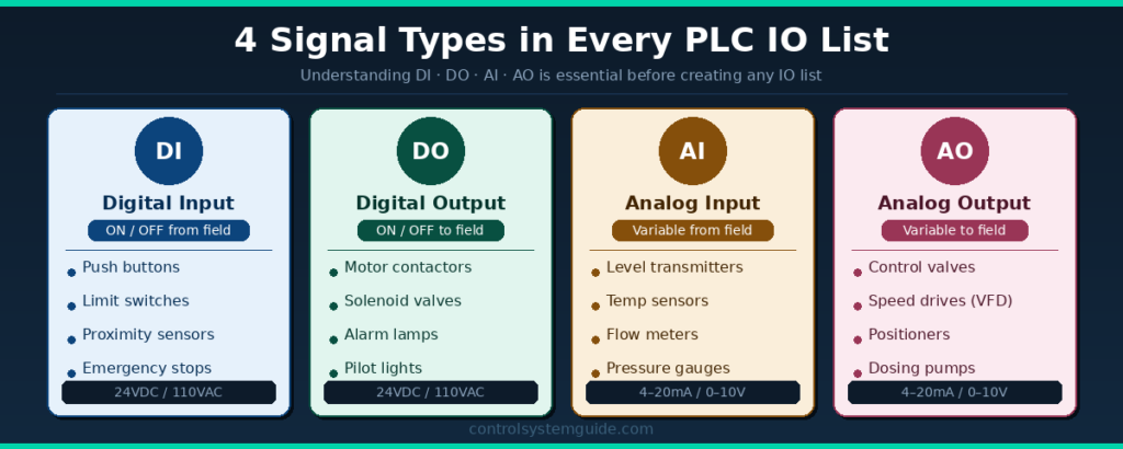
Every PLC IO list uses four signal types. Understanding the difference between them is essential before creating any IO list.
Digital Input (DI) An ON/OFF signal received by the PLC from a field device. Examples: push buttons, limit switches, proximity sensors, emergency stops, level switches. Typical voltage: 24VDC or 110VAC.
Digital Output (DO) An ON/OFF signal sent by the PLC to control a field device. Examples: motor contactors, solenoid valves, alarm lamps, pilot lights. Typical voltage: 24VDC.
Analog Input (AI) A continuously variable signal received by the PLC from a field transmitter. Examples: temperature transmitters, pressure transmitters, flow meters, level transmitters. Typical signal: 4–20mA or 0–10V.
Analog Output (AO) A continuously variable signal sent by the PLC to control a field device. Examples: control valves, variable frequency drives (VFDs), positioners, dosing pumps. Typical signal: 4–20mA or 0–10V.
Why PLC IO Lists Are Critical in Automation Projects
The PLC IO list is created at the very beginning of a project and updated throughout design, installation, and commissioning. It serves as the single source of truth for all signal information.
During design: The IO list determines how many PLC modules are needed, which directly affects hardware costs. Engineers use PLC IO calculation to count signals and select the right PLC hardware.
During panel build: Electricians use the IO list to wire every field cable to the correct PLC terminal.
During programming: PLC programmers use tag names and addresses from the IO list to write control logic without confusion.
During commissioning: Engineers test each signal one by one against the IO list to verify correct wiring and function.
During maintenance: Fault finding becomes much faster when every signal is documented with its description, address, and cable number.
IO List for PLC – 7 Real PLC IO List Examples
An io list for plc applies the same standard structure across every industrial sector. The plc io list examples below cover the 7 most common applications automation engineers encounter on real industrial projects — from simple motor control to complete water treatment plants. Each io list example shows the typical signal breakdown, field devices, and total IO point count to help you size your PLC accurately.
Here are 7 complete PLC IO list examples from real industrial applications. Each example includes a full table with tag names, descriptions, signal types, PLC addresses, and additional data.
Example 1 – Motor Control System
The most common PLC IO list in industrial automation. Used for conveyor motors, pump motors, compressors, and fan systems worldwide.
| Tag Name | Description | Type | PLC Address | Cable No. |
|---|---|---|---|---|
| START_PB | Start Push Button | DI | I0.0 | W001 |
| STOP_PB | Stop Push Button | DI | I0.1 | W002 |
| E_STOP | Emergency Stop Button | DI | I0.2 | W003 |
| MTR_01_FB | Motor Run Feedback | DI | I0.3 | W004 |
| OL_TRIP | Overload Trip Signal | DI | I0.4 | W005 |
| MTR_01_RUN | Motor Contactor Output | DO | Q0.0 | W006 |
| ALARM_LIGHT | Fault Alarm Indicator | DO | Q0.1 | W007 |
Total: 5 DI, 2 DO
Example 2 – Tank Level Control System
Used in water treatment, chemical processing, food & beverage, and oil & gas industries. Includes analog signals for continuous level measurement and valve control.
| Tag Name | Description | Type | PLC Address | Signal Range |
|---|---|---|---|---|
| LT_101 | Tank Level Transmitter | AI | IW0 | 4–20mA |
| PT_101 | Inlet Pressure Transmitter | AI | IW2 | 4–20mA |
| HS_101_HIGH | High Level Switch | DI | I0.0 | 24VDC |
| LS_101_LOW | Low Level Switch | DI | I0.1 | 24VDC |
| FCV_101 | Feed Control Valve | AO | QW0 | 4–20mA |
| SOV_101 | Drain Solenoid Valve | DO | Q0.0 | 24VDC |
| HH_ALARM | High-High Level Alarm | DO | Q0.1 | 24VDC |
Total: 2 DI, 2 DO, 2 AI, 1 AO
Example 3 – Conveyor System
Standard PLC IO list for belt conveyors, roller conveyors, and sorting systems in manufacturing and warehousing applications.
| Tag Name | Description | Type | PLC Address | Notes |
|---|---|---|---|---|
| START_CONV | Conveyor Start Button | DI | I0.0 | NO Contact |
| STOP_CONV | Conveyor Stop Button | DI | I0.1 | NC Contact |
| JAM_SENSOR | Jam Detection Sensor | DI | I0.2 | Proximity |
| SPEED_REF | VFD Speed Reference | AO | QW0 | 4–20mA |
| CONV_RUN | Conveyor Motor Output | DO | Q0.0 | 24VDC |
| SPEED_FB | Motor Speed Feedback | AI | IW0 | 4–20mA |
| JAM_ALARM | Jam Alarm Output | DO | Q0.1 | 24VDC |
Total: 3 DI, 2 DO, 1 AI, 1 AO
Example 4 – Siemens S7-1200 / S7-1500 IO List Format
This is the standard PLC IO list format used with Siemens S7-1200 and S7-1500 PLCs programmed in TIA Portal. Siemens uses % prefix addressing format.
| Tag Name | Description | Type | Siemens Address | Module |
|---|---|---|---|---|
| START_PB | Start Push Button | DI | %I0.0 | DI Module |
| STOP_PB | Stop Push Button | DI | %I0.1 | DI Module |
| E_STOP | Emergency Stop | DI | %I0.2 | DI Module |
| MOTOR_RUN | Motor Contactor | DO | %Q0.0 | DO Module |
| FAULT_LIGHT | Fault Indicator Lamp | DO | %Q0.1 | DO Module |
| TEMP_SENSOR | Temperature Transmitter | AI | %IW64 | AI Module |
| VALVE_CTRL | Control Valve Output | AO | %QW64 | AO Module |
💡 Siemens TIA Portal Tip: Always use the % prefix in Siemens addressing (%I, %Q, %IW, %QW). The module slot position determines the starting address. Slot 1 DI starts at %I0.0, AI modules typically start at %IW64.
Total: 3 DI, 2 DO, 1 AI, 1 AO
Example 5 – Allen-Bradley / Rockwell Studio 5000 IO List
Tag-based IO list format used for Allen-Bradley ControlLogix and CompactLogix PLCs in Studio 5000 Logix Designer. Rockwell uses descriptive tag names instead of fixed addresses.
| Tag Name | Description | Type | Data Type | Module Slot |
|---|---|---|---|---|
| Motor1_Start | Motor 1 Start Button | DI | BOOL | Slot 1 |
| Motor1_Stop | Motor 1 Stop Button | DI | BOOL | Slot 1 |
| Motor1_EStop | Emergency Stop | DI | BOOL | Slot 1 |
| Motor1_Run | Motor 1 Contactor | DO | BOOL | Slot 2 |
| Motor1_Fault | Motor Fault Indicator | DO | BOOL | Slot 2 |
| Tank1_Level | Tank Level (4–20mA) | AI | REAL | Slot 3 |
| Valve1_Ctrl | Control Valve Output | AO | REAL | Slot 4 |
💡 Rockwell Studio 5000 Tip: Allen-Bradley uses tag-based addressing — there are no fixed I0.0/Q0.0 addresses. Tag names must be unique across the program. Follow ISA-5.1 naming conventions for professional projects (e.g., FT-101 for Flow Transmitter loop 101).
Total: 3 DI, 2 DO, 1 AI, 1 AO
Example 6 – HVAC / Building Automation IO List
Used in building management systems for air handling units (AHUs), chillers, boilers, and variable air volume (VAV) systems.
| Tag Name | Description | Type | Address | Engineering Unit |
|---|---|---|---|---|
| SAT_101 | Supply Air Temperature | AI | IW0 | °C (4–20mA) |
| RAT_101 | Return Air Temperature | AI | IW2 | °C (4–20mA) |
| DP_101 | Duct Static Pressure | AI | IW4 | Pa (4–20mA) |
| AHU_01_RUN | AHU Fan Run Command | DO | Q0.0 | 24VDC |
| AHU_01_FB | AHU Fan Run Feedback | DI | I0.0 | 24VDC |
| DAMP_01 | Outside Air Damper | AO | QW0 | 0–10V |
| COOL_VALVE | Cooling Coil Valve | AO | QW2 | 4–20mA |
| FIRE_TRIP | Fire Alarm Trip Input | DI | I0.1 | 24VDC |
Total: 2 DI, 1 DO, 3 AI, 2 AO
Example 7 – Water Treatment Plant IO List
Used in municipal water treatment facilities, pumping stations, and wastewater treatment plants. These systems typically have hundreds of IO points.
| Tag Name | Description | Type | Address | Signal Range |
|---|---|---|---|---|
| FT_101 | Inlet Flow Transmitter | AI | IW0 | 4–20mA |
| CL_101 | Chlorine Analyzer | AI | IW2 | 4–20mA |
| PT_101 | Pump Discharge Pressure | AI | IW4 | 4–20mA |
| LS_SUMP | Sump Low Level Switch | DI | I0.0 | 24VDC |
| PUMP_01_FB | Pump 1 Run Feedback | DI | I0.1 | 24VDC |
| PUMP_01_RUN | Pump 1 Run Command | DO | Q0.0 | 24VDC |
| DOSING_PUMP | Chemical Dosing Pump | DO | Q0.1 | 24VDC |
| HH_FLOW | High-High Flow Alarm | DO | Q0.2 | 24VDC |
Total: 2 DI, 3 DO, 3 AI
How to Use These IO List for PLC Examples for Your Project
The 7 PLC IO list examples above cover the most common applications. To estimate your full project’s io list for plc requirement, use this quick calculation method based on the number of devices in your system:
| Device Type | Typical IO per Device | Used in Application |
|---|---|---|
| Single motor / pump / fan | 8 IO points | Motor control circuit |
| Conveyor with VFD | 14 IO points | Belt or roller conveyor |
| Tank with level control | 12 IO points | Process tank, water tank, chemical tank |
| Heat exchanger | 8-10 IO points | Heating / cooling loop |
| HVAC zone | 10-15 IO points | Air handling unit, chiller circuit |
| Packaging machine | 20-30 IO points | Filling, labeling, wrapping |
Quick estimation formula: Total IO Count = (Number of Motors × 8) + (Number of Conveyors × 14) + (Number of Tanks × 12) + 25% spare capacity
💡 Example: A small project with 5 motors, 2 conveyors, and 3 tanks would need approximately (5 × 8) + (2 × 14) + (3 × 12) = 40 + 28 + 36 = 104 IO points base + 25% spare = 130 total IO points. Use this quick calculation at the quotation stage to size your PLC and order hardware confidently.
For complete IO count calculation methodology read: PLC I/O Count Calculation Guide
Download Free PLC IO List Excel Template
👉 Download Free PLC IO List Excel Template
The free template includes columns for:
- Tag Name
- Signal Description
- Signal Type (DI / DO / AI / AO)
- PLC Address
- Cable Number
- Engineering Notes
Download it, customize it for your project, and reuse it on every automation job.
How to Create a PLC IO List – Step by Step
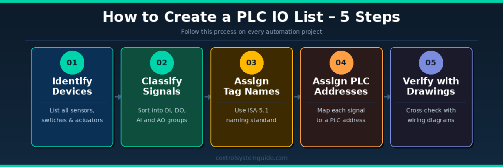
Follow these 5 steps on every automation project to create a complete and accurate PLC IO list.
Step 1 – Identify All Field Devices Walk through the P&ID (Piping and Instrumentation Diagram) or machine layout and list every device that connects to the PLC. This includes sensors, push buttons, switches, motors, valves, and transmitters.
Step 2 – Classify Signal Types For each device, determine whether it is a DI, DO, AI, or AO signal. Digital signals are ON/OFF. Analog signals are continuously variable (4–20mA or 0–10V).
Step 3 – Assign Tag Names Give each signal a unique tag name following the ISA-5.1 naming standard. Example: FT-101 (Flow Transmitter, Loop 101), LV-201 (Level Valve, Loop 201). Consistent tag naming makes programming and troubleshooting much faster.
Step 4 – Assign PLC Addresses Map each signal to a specific PLC hardware address based on the module slot and channel number. For Siemens: %I0.0, %Q0.0, %IW64. For standard IEC format: I0.0, Q0.0, IW0.
Step 5 – Verify Against Electrical Drawings Cross-check every row in the IO list against the control panel wiring diagrams and field cable schedules. Discrepancies at this stage are far cheaper to fix than after panel wiring is complete.
💡 Pro Tip: Always add 15–20% spare IO capacity to your final IO count. Projects always grow during detailed design and commissioning. Spare IO saves you from ordering additional modules later at much higher cost.
For more detail on counting IO signals correctly, read our guide on PLC IO Calculation.
Frequently Asked Questions – PLC IO List
What is a PLC IO list? A PLC IO list (Input Output list) is a document used in industrial automation to define every signal connected to a PLC system. It records field devices such as sensors, switches, motors, and valves along with their signal type (DI/DO/AI/AO), PLC address, and cable reference. It is one of the most essential documents in any automation project.
What does IO stand for in PLC? IO stands for Input and Output. Inputs are signals the PLC receives from field devices such as sensors and switches. Outputs are signals the PLC sends to control devices such as motors, valves, and indicator lamps. Together they define how the PLC interacts with the physical process.
What information is included in a PLC IO list? A standard PLC IO list includes: tag name, signal description, signal type (DI/DO/AI/AO), PLC hardware address, cable number, engineering unit (°C, bar, m³/h), and any engineering notes. Some templates also include module slot, channel number, and spare status.
What is the difference between DI, DO, AI, and AO? DI (Digital Input) is an ON/OFF signal from a field device to the PLC. DO (Digital Output) is an ON/OFF signal from the PLC to a field device. AI (Analog Input) is a variable signal (4–20mA or 0–10V) from a transmitter to the PLC. AO (Analog Output) is a variable signal from the PLC to a control device such as a valve or VFD.
What format is a PLC IO list made in? Most automation engineers create PLC IO lists in Microsoft Excel. Excel allows easy sorting, filtering, and sharing between engineering teams. Some large projects use dedicated tools like EPLAN Electric P8 or AutoCAD Electrical which can generate IO lists directly from the schematic.
How many IO points should a PLC IO list include? There is no fixed number — it depends entirely on the size of the system. A small machine may have 20–50 IO points. A medium industrial plant typically has 200–500 IO points. Large facilities such as power plants or refineries can have thousands. Always add 15–20% spare IO capacity to the final count.
What is the difference between a PLC IO list and a PLC tag list? A PLC IO list maps physical field devices to PLC hardware addresses. A PLC tag list assigns software variable names to those hardware addresses inside the PLC program. In modern platforms like Siemens TIA Portal and Rockwell Studio 5000, both are combined into a single tag database where physical addresses and tag names are defined together.
What naming convention should I use for IO list tags? The ISA-5.1 standard is the most widely used naming convention in industrial automation. The format is: Instrument Type Code + Loop Number. Examples: FT-101 (Flow Transmitter, Loop 101), PT-202 (Pressure Transmitter, Loop 202), LV-301 (Level Valve, Loop 301). Always use consistent, descriptive names that identify both the signal function and location.
Conclusion
A well-structured PLC IO list is essential for every industrial automation project. It connects field devices to PLC hardware, guides panel wiring, supports PLC programming, and speeds up commissioning and maintenance.
Whether you are working on a small machine with 30 IO points or a large plant with 500+ signals, using a structured IO list format from the start saves significant time and prevents costly errors.
Download the free Excel template below and start organizing your signals the right way.
👉 Download Free PLC IO List Excel Template
Related Guides:
- PLC IO List Example – 3 Real Industrial Cases
- PLC Inputs and Outputs Explained – DI, DO, AI, AO
- PLC IO Calculation – Step by Step
- Complete PLC Programming Guide for Beginners
Automation engineer based in Asia, with hands-on experience in PLC programming, SCADA, and industrial control systems across oil and gas, power, food and beverage, and water industries. Writes about PLC fundamentals, ladder logic, vendor-specific instruction sets for Siemens, Allen-Bradley, and other major platforms, and industrial communication protocols.