Last Updated: April 2026 | Written for automation engineers working on real industrial projects.
A PLC IO list example is the fastest way to understand how real industrial automation systems are structured and documented in practice.
In this guide you will find 5 complete PLC IO list examples from real industries — each with a full signal table, tag names, PLC addresses, and engineering notes. You will also learn the most common IO list mistakes engineers make and how to avoid them.
Before diving into examples, if you want a complete explanation of what a PLC IO list is and how to create one from scratch, read: PLC IO List Explained – Free Excel Template
What Makes a Good PLC IO List? (Quick Recap)
Before looking at examples, a well-structured PLC IO list must include these key columns in every row:
| Column | Purpose | Example |
|---|---|---|
| Tag Name | Unique identifier for the signal | LT_101, MTR_01_RUN |
| Description | Clear plain-language label | Tank Level Transmitter |
| Signal Type | DI / DO / AI / AO | AI |
| PLC Address | Hardware memory location | IW0, %I0.0 |
| Cable No. | Field cable reference | W001 |
| Signal Range | Voltage or current spec | 4–20mA, 24VDC |
| Notes | Engineering remarks | NC Contact, Spare |
The more complete each row, the faster your project moves from design through commissioning. Now let’s look at real examples.
PLC IO List Example 1 – Conveyor System
Conveyor systems are one of the most common PLC applications in manufacturing, warehousing, and food processing. This IO list example covers a standard belt conveyor with start/stop control, jam detection, and variable speed drive.
| Tag Name | Description | Type | PLC Address | Signal Range | Cable No. |
|---|---|---|---|---|---|
| START_PB | Conveyor Start Push Button | DI | I0.0 | 24VDC NO | W001 |
| STOP_PB | Conveyor Stop Push Button | DI | I0.1 | 24VDC NC | W002 |
| E_STOP | Emergency Stop Button | DI | I0.2 | 24VDC NC | W003 |
| JAM_SENS | Belt Jam Detection Sensor | DI | I0.3 | 24VDC Prox | W004 |
| MTR_OL | Motor Overload Trip | DI | I0.4 | 24VDC NC | W005 |
| CONV_RUN | Conveyor Motor Contactor | DO | Q0.0 | 24VDC | W006 |
| JAM_ALARM | Jam Alarm Indicator Lamp | DO | Q0.1 | 24VDC | W007 |
| SPEED_REF | VFD Speed Reference Signal | AO | QW0 | 4–20mA | W008 |
| SPEED_FB | Motor Speed Feedback | AI | IW0 | 4–20mA | W009 |
IO Summary: 5 DI | 2 DO | 1 AI | 1 AO | Total: 9 points
💡 Engineering Note: Always use NC (Normally Closed) contacts for stop buttons and emergency stops in your IO list. This ensures the PLC sees a fault if the cable is cut or disconnected — a critical safety requirement in all industrial automation systems.
PLC IO List Example 2 – Water Treatment Plant
Water treatment systems involve a mix of digital and analog signals for level measurement, pump control, flow monitoring, and chemical dosing. This is a typical IO list example for a municipal pumping station.
| Tag Name | Description | Type | PLC Address | Signal Range | Engineering Unit |
|---|---|---|---|---|---|
| FT_101 | Inlet Flow Transmitter | AI | IW0 | 4–20mA | m³/h |
| LT_101 | Reservoir Level Transmitter | AI | IW2 | 4–20mA | m |
| PT_101 | Pump Discharge Pressure | AI | IW4 | 4–20mA | bar |
| CL_101 | Chlorine Residual Analyzer | AI | IW6 | 4–20mA | mg/L |
| LS_LOW | Reservoir Low Level Switch | DI | I0.0 | 24VDC | – |
| LS_HIGH | Reservoir High Level Switch | DI | I0.1 | 24VDC | – |
| PUMP_01_FB | Pump 1 Run Feedback | DI | I0.2 | 24VDC | – |
| PUMP_02_FB | Pump 2 Run Feedback | DI | I0.3 | 24VDC | – |
| PUMP_01_RUN | Pump 1 Start Command | DO | Q0.0 | 24VDC | – |
| PUMP_02_RUN | Pump 2 Start Command | DO | Q0.1 | 24VDC | – |
| DOSE_PUMP | Chemical Dosing Pump | DO | Q0.2 | 24VDC | – |
| HH_ALARM | High-High Level Alarm Output | DO | Q0.3 | 24VDC | – |
| FCV_101 | Inlet Flow Control Valve | AO | QW0 | 4–20mA | % |
IO Summary: 4 DI | 4 DO | 4 AI | 1 AO | Total: 13 points
💡 Engineering Note: In water treatment IO lists, always include the engineering unit column for every analog signal. Operators and SCADA engineers need to know whether a level signal is in meters, percent, or millimeters before they can configure alarm limits correctly.
PLC IO List Example 3 – Motor Control Centre (MCC)
Motor Control Centres manage multiple motors from a single PLC panel. This IO list example covers a 3-motor MCC panel typical in pumping stations, manufacturing plants, and HVAC systems.
| Tag Name | Description | Type | PLC Address | Cable No. | Notes |
|---|---|---|---|---|---|
| MTR01_START | Motor 1 Start Command | DO | Q0.0 | W001 | – |
| MTR01_STOP | Motor 1 Stop Command | DO | Q0.1 | W002 | – |
| MTR01_FB | Motor 1 Run Feedback | DI | I0.0 | W003 | Aux contact |
| MTR01_OL | Motor 1 Overload Trip | DI | I0.1 | W004 | NC contact |
| MTR02_START | Motor 2 Start Command | DO | Q0.2 | W005 | – |
| MTR02_STOP | Motor 2 Stop Command | DO | Q0.3 | W006 | – |
| MTR02_FB | Motor 2 Run Feedback | DI | I0.2 | W007 | Aux contact |
| MTR02_OL | Motor 2 Overload Trip | DI | I0.3 | W008 | NC contact |
| MTR03_START | Motor 3 Start Command | DO | Q0.4 | W009 | – |
| MTR03_FB | Motor 3 Run Feedback | DI | I0.4 | W010 | Aux contact |
| MTR03_OL | Motor 3 Overload Trip | DI | I0.5 | W011 | NC contact |
| MCC_FAULT | MCC Common Fault Alarm | DO | Q0.5 | W012 | To HMI |
| SPARE_DI_01 | Spare Digital Input | DI | I0.6 | – | Spare |
| SPARE_DO_01 | Spare Digital Output | DO | Q0.6 | – | Spare |
IO Summary: 6 DI + 1 Spare DI | 6 DO + 1 Spare DO | Total: 14 points
💡 Engineering Note: Notice the spare IO rows at the bottom. This is best practice — always document spare channels in your IO list so the panel builder wires them to terminals even if they are unused. This makes future expansion much easier and cheaper.
PLC IO List Example 4 – Siemens S7-1500 Format (TIA Portal)
This PLC IO list example shows the exact format used when working with Siemens S7-1500 PLCs in TIA Portal. Siemens uses the % prefix for all addresses and organizes signals by module slot.
| Tag Name | Description | Type | Siemens Address | Module Slot | Signal Range |
|---|---|---|---|---|---|
| PUMP_START | Pump Start Button | DI | %I0.0 | Slot 1 – DI32 | 24VDC |
| PUMP_STOP | Pump Stop Button | DI | %I0.1 | Slot 1 – DI32 | 24VDC |
| E_STOP_01 | Emergency Stop Zone 1 | DI | %I0.2 | Slot 1 – DI32 | 24VDC NC |
| PUMP_FB | Pump Contactor Feedback | DI | %I0.3 | Slot 1 – DI32 | 24VDC |
| PUMP_RUN | Pump Motor Contactor | DO | %Q0.0 | Slot 2 – DO32 | 24VDC |
| PUMP_FAULT | Pump Fault Indicator | DO | %Q0.1 | Slot 2 – DO32 | 24VDC |
| LT_TANK | Tank Level Transmitter | AI | %IW64 | Slot 3 – AI8 | 4–20mA |
| TT_OUTLET | Outlet Temperature Sensor | AI | %IW66 | Slot 3 – AI8 | 4–20mA |
| FCV_INLET | Inlet Flow Control Valve | AO | %QW64 | Slot 4 – AO4 | 4–20mA |
IO Summary: 4 DI | 2 DO | 2 AI | 1 AO | Total: 9 points
💡 Siemens TIA Portal Note: In TIA Portal, AI module addresses start at %IW64 for Slot 3 and AO addresses start at %QW64 for Slot 4. This offset is because slots 1 and 2 (DI/DO) occupy address bytes 0–63. Always check your hardware configuration in TIA Portal to confirm the exact start address for each module.
PLC IO List Example 5 – Oil & Gas Plant (Advanced Format)
Large oil and gas facilities use detailed IO lists with alarm limits, SIL ratings, cable specifications, and calibration data. This example shows a more advanced IO list format used in process industries.
| Tag Name | Description | Type | Address | Range | LL Alarm | L Alarm | H Alarm | HH Alarm | SIL |
|---|---|---|---|---|---|---|---|---|---|
| PT_201 | Separator Inlet Pressure | AI | IW0 | 0–100 bar | 5 bar | 10 bar | 80 bar | 90 bar | SIL2 |
| TT_201 | Separator Temperature | AI | IW2 | 0–200°C | 20°C | 30°C | 150°C | 170°C | SIL1 |
| LT_201 | Separator Level | AI | IW4 | 0–100% | 5% | 15% | 80% | 90% | SIL2 |
| FT_201 | Gas Outlet Flow | AI | IW6 | 0–5000 Nm³/h | – | 100 | 4500 | 4800 | – |
| XV_201_OP | Inlet Shutdown Valve Open | DI | I0.0 | 24VDC | – | – | – | – | SIL2 |
| XV_201_CL | Inlet Shutdown Valve Closed | DI | I0.1 | 24VDC | – | – | – | – | SIL2 |
| XV_201_CMD | Inlet Valve Open Command | DO | Q0.0 | 24VDC | – | – | – | – | SIL2 |
| FCV_201 | Gas Outlet Control Valve | AO | QW0 | 4–20mA | – | – | – | – | – |
| ESD_TRIP | Emergency Shutdown Trip | DI | I0.2 | 24VDC NC | – | – | – | – | SIL3 |
IO Summary: 3 DI + 1 ESD | 1 DO | 4 AI | 1 AO | Total: 9 points
💡 Oil & Gas Note: In process industries, the IO list must include alarm setpoints (LL, L, H, HH) and Safety Integrity Level (SIL) ratings for every signal. These values come directly from the Process Hazard Analysis (PHA) and are used by the control system engineer to configure alarm management in the SCADA system.
6 Common PLC IO List Mistakes to Avoid
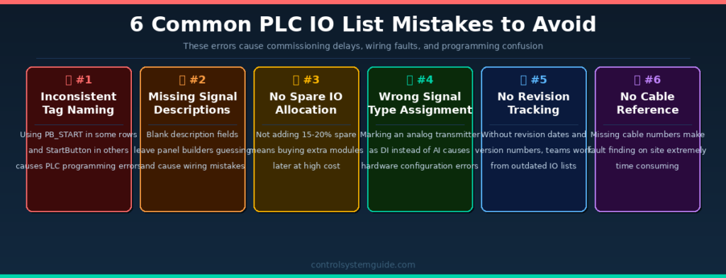
Even experienced engineers make these mistakes. Catching them early saves days of rework during commissioning.
Mistake 1 – Inconsistent Tag Naming
Using different naming formats in the same IO list (e.g., PB_START in one row and StartButton in another) causes confusion in PLC programming and SCADA configuration. Pick one convention — ISA-5.1 is the industry standard — and apply it to every row without exception.
Mistake 2 – Missing Signal Descriptions
Leaving the description field blank or using vague labels like “DI 1” or “Pump signal” forces panel builders and programmers to guess what each signal does. Every row must have a clear, plain-language description that anyone on the project can understand.
Mistake 3 – No Spare IO Allocation
Designing an IO list with zero spare channels means the moment a client adds one more sensor during detailed design, you have to order additional PLC modules, redesign the panel, and delay delivery. Always add 15–20% spare IO to every module.
Mistake 4 – Wrong Signal Type Assignment
Marking a 4–20mA pressure transmitter as DI instead of AI is one of the most common errors for junior engineers. It leads to ordering the wrong PLC module type. Always confirm the signal type directly from the instrument datasheet before filling in the IO list.
Mistake 5 – No Revision Tracking
An IO list without a revision history is a project risk. When multiple engineers update the same document without tracking changes, teams end up wiring panels from outdated versions. Always include a revision column with date, version number, and description of changes.
Mistake 6 – Missing Cable Numbers
Without cable reference numbers in the IO list, fault finding on a live plant becomes extremely time consuming. Every signal row must reference the cable number that connects the field device to the PLC terminal — this is essential for maintenance and troubleshooting.
PLC IO List Example Excel Format – What to Include
The most practical format for a PLC IO list is Microsoft Excel. Here is the recommended column structure used in real industrial projects:
| # | Column Name | Required | Example |
|---|---|---|---|
| 1 | Serial Number | ✅ Yes | 1, 2, 3… |
| 2 | Tag Name | ✅ Yes | LT_101 |
| 3 | Description | ✅ Yes | Tank Level Transmitter |
| 4 | Signal Type | ✅ Yes | AI |
| 5 | PLC Address | ✅ Yes | IW0 / %IW64 |
| 6 | Signal Range | ✅ Yes | 4–20mA |
| 7 | Engineering Unit | ✅ Yes | m, °C, bar, % |
| 8 | Cable Number | ✅ Yes | W001 |
| 9 | Module / Slot | ⚠️ Recommended | Slot 3, Ch 0 |
| 10 | Alarm Limits | ⚠️ Recommended | L=10%, H=85% |
| 11 | Spare Status | ⚠️ Recommended | Active / Spare |
| 12 | Revision | ⚠️ Recommended | Rev A, Apr 2026 |
👉 Download Free PLC IO List Excel Template — includes all essential columns ready to use.
👉 Download Professional IO List Template – $5 — includes automatic DI/DO/AI/AO counting, dropdowns, cable tracking, and spare IO management.
How to Read a PLC IO List – For Beginners
If you are new to automation, here is how to read any PLC IO list example correctly:
Step 1 – Read the Tag Name first. The tag name tells you what instrument or device this signal belongs to. FT_101 means Flow Transmitter, Loop 101. LT_201 means Level Transmitter, Loop 201.
Step 2 – Check the Signal Type. DI and DO are simple ON/OFF signals. AI and AO carry variable measurements like temperature, pressure, or flow rate.
Step 3 – Note the PLC Address. This is where the signal lives in PLC memory. I0.0 is a digital input. IW0 is an analog input word. Q0.0 is a digital output. QW0 is an analog output word.
Step 4 – Check the Signal Range. This tells you the electrical specification. 24VDC means it’s a 24-volt digital signal. 4–20mA means it’s a standard analog current loop. 0–10V means it’s a voltage-based analog signal.
For the complete step-by-step process of creating an IO list, read: PLC IO List Explained – Full Guide
Frequently Asked Questions – PLC IO List Example
What is a PLC IO list example used for?
A PLC IO list example is used to show engineers how real industrial automation systems are documented and structured. It provides a practical reference for signal naming, PLC addressing, and IO list formatting that can be directly applied to new projects.
What is included in a real PLC IO list example?
A real PLC IO list example includes tag names, signal descriptions, signal types (DI/DO/AI/AO), PLC hardware addresses, cable references, signal ranges (4–20mA, 24VDC), engineering units, and spare IO allocation. Advanced examples also include alarm limits and SIL safety ratings.
What is the difference between DI and AI in a PLC IO list?
DI (Digital Input) is an ON/OFF signal — for example, a push button or level switch. AI (Analog Input) is a continuously variable signal — for example, a 4–20mA pressure transmitter or temperature sensor that gives a range of values rather than just ON or OFF.
How many columns should a PLC IO list have?
A basic PLC IO list needs at least 6 columns: tag name, description, signal type, PLC address, signal range, and cable number. A professional IO list for large industrial projects can have 12 to 21 columns including alarm limits, SIL ratings, module slot, revision tracking, and spare status.
What naming convention is used in PLC IO list examples?
The ISA-5.1 standard is the most widely used naming convention. The format combines an instrument function code with a loop number — for example, FT-101 for Flow Transmitter Loop 101, or LV-201 for Level Valve Loop 201. This convention is used in oil and gas, water treatment, and manufacturing industries worldwide.
Can I download a free PLC IO list example in Excel format?
Yes. You can download a free PLC IO list Excel template from this page. The free template includes all essential columns and is ready to customize for your project. A professional version with automatic IO counting, dropdown menus, and cable tracking is also available for $5.
What is the difference between a simple and advanced PLC IO list?
A simple PLC IO list covers basic columns — tag, description, type, and address. An advanced IO list used in process industries adds alarm setpoints (LL/L/H/HH), SIL safety ratings, calibration ranges, engineering units, cable specifications, and revision history. The level of detail depends on the project size and industry requirements.
How do I assign PLC addresses in an IO list?
PLC addresses are assigned based on the module type and slot position in the PLC rack. For Siemens S7-1200/1500, digital inputs start at %I0.0 and analog inputs typically start at %IW64 depending on the slot. For standard IEC format, digital inputs start at I0.0 and analog inputs at IW0. Always verify addresses against your PLC hardware configuration before finalizing the IO list.
Conclusion
A well-structured PLC IO list example shows you exactly how professional automation engineers organize and document every signal in a real project. Whether you are working on a simple conveyor system with 10 IO points or a large oil and gas plant with thousands of signals, the principles are the same — clear tag names, correct signal types, proper addresses, and complete documentation.
Use the 5 examples in this guide as templates for your own projects. Download the free Excel template and start building your IO list the right way from day one.
👉 Download Free PLC IO List Excel Template
👉 Download Professional IO List Template – $5
Related Guides: